OBJECTIVE
Ametherm inrush current limiters are used in many applications today that require suppression of surge current when power is first applied to the system. One of the popular applications of Ametherm inrush current limiters is in power factor correction circuits. This article provides a solution for finding the correct power factor correction (PFC) circuit for an inductive load. This solution is suitable for applications that include ballasts, LED drivers, and HVAC.
Background
The power factor (PF) describes the characteristics of AC circuits in fluorescent lamps, appliances, transformers, relays, and motors. It is a ratio between the power that does the actual work and the power that is delivered to the equipment. It is a dimensionless entity with a value varying, theoretically, between 0 and 1. A practical value of the PF, in the real world, varies between 0.65 and 1. When its value is less than 1, additional power is required to operate electrical components such as transformers, induction motors, or high-intensity discharge lighting.
Mathematically speaking, PF or Cos (α) = true power in W/apparent power – rms voltage x rms current (as measured), or XR/Z where the angle α denotes the phase angle between the voltage and the current waveform.
Apparent power (in volt-ampere(VA)) denotes a quantity where voltage is multiplied by current. Real power, however, is measured with the help of a watt meter.
As shown in Figure 1 below, Z is the vector addition of XR (reactive power or real power) and XL (inductive power or apparent power).
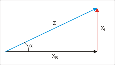
Figure 1: Z is the vector addition of XR and XL
Figure 2 shows how larger inductive loads (requiring large reactive power) result in a larger angle α (measured between XR and Z). This implies that large inductive loads result in a smaller quantitative PF value.
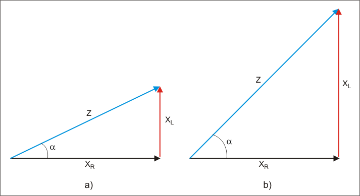
Figure 2: The Cos α for b) has a smaller value than the Cos α for a)
NOTE:
Most equipment built today carries an inductive load, as opposed to a resistive load. When that occurs, the voltage and current become out of phase due to the resistance. The product of the voltage and current is called the apparent power. This is commonly referred to in VA instead of watts since watts are reserved for real power.
Real power can be considered as resistive power, which is dissipated as heat. A reactance from the inductive load does not dissipate power, but stores energy in the electric or magnetic field.
Alternatively, the PF is the ratio of real power to apparent power.
Theory of Mitigating an Inductive Load With a Capacitor
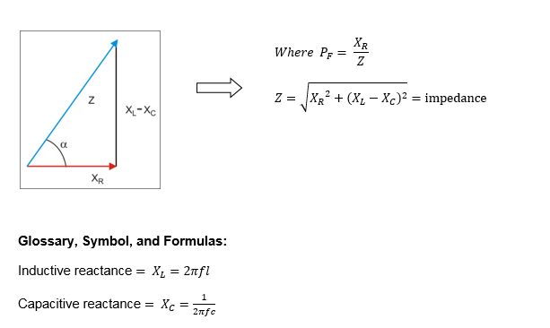
When both inductance and capacitance are present in an electrical circuit, XL and XC are added or subtracted algebraically, because they are out of phase by 180º. The vector triangle or phasor triangle is as shown below:
Problem Statement
The following circuit exhibits the typical behavior of an inductive circuit where the inductive component of the current lags the voltage in the main line.
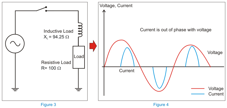
Figures 3 and 4: The inductive component of the current lags the voltage in the main line
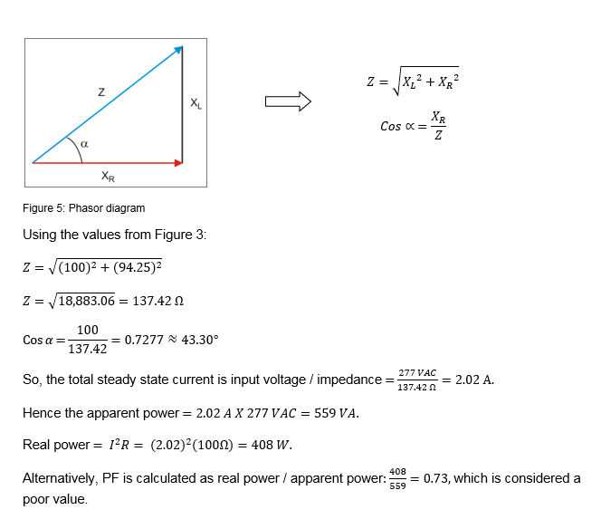
The first step is to determine the PF for the above circuit, which is calculated using the phasor diagram, as shown in Figure 5.
Solution
A power factor correction (PFC) circuit is able to correct this poor PF.
In order to correct this condition, a parallel capacitor is added across the inductive load. This is shown in Figure 6, with the resultant phasor diagram shown in Figure 7. The capacitive current attempts to lead the voltage by 90º and cancels the lagging inductive current, which is about 43.30º.
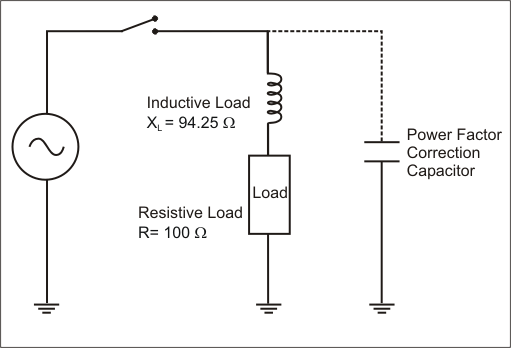
Figure 6: A parallel capacitor is added across the inductive load
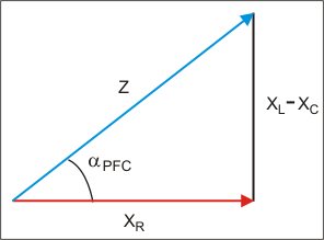
Figure 7: Phasor diagram
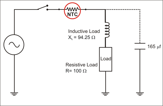
Figure 8: An NTC thermistor is added to limit the inrush current
Next, turning on the capacitor will act like a short and induce a huge inrush current. The best way to limit the inrush current is to introduce an NTC thermistor, as shown in Figure 8. Note that this NTC thermistor must handle 2.02 A of steady state current.
Let’s consider a target (design) PF value for the PFC circuit of 0.8
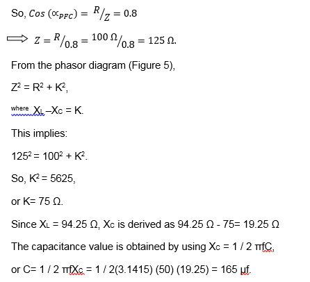
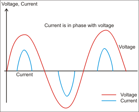
Figure 9: The current is in phase with the voltage
The energy needed to block the inrush current without self-destruction is E= ½ C V2
= ½ (2.77 x 1.414V)2 (165 / 1,000,000) = 12.70 J.
Selection of Thermistor
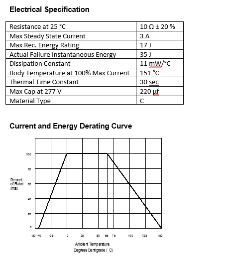
Ametherm offers a number of thermistors. In order to handle this inrush current, the best selection is:
Thermistor type: SL10 10003 (See Appendix A)
UL File: E209153
CSA File: CA110863
Rated for 277 VAC & 3.0 A
Appendix A