- A transformer draws inrush current that can exceed saturation current at power up.
- The Inrush Current affects the magnetic property of the core.
- This happens even if the transformer has no load with its secondary open.
- The magnitude of the inrush current depends on the point on the AC wave the transformer is switched on.
- If turn-on occurs when the AC voltage wave is at its peak value, there will be no inrush current drawn by the transformer. The magnitude of the current in this case will be at normal no load value.
- If at turn-on, the AC wave is going through its zero value, then the current drawn will be very high and exceed the saturation current (see Figure 1).
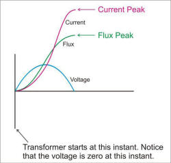
In this scenario, the transformer has to be protected from inrush current.
Protection of the Transformer
This application note provides a convenient solution (see Figure 2) to deal with the problem of inrush current exceeding saturation current in transformers.
The solution uses an NTC Thermistor in series with the primary.
This NTC Thermistor offers high resistance at the beginning of switching and limits the inrush current.
After a short time, the NTC Thermistor resistance decreases to a low value due to self heating and does not affect normal operation.
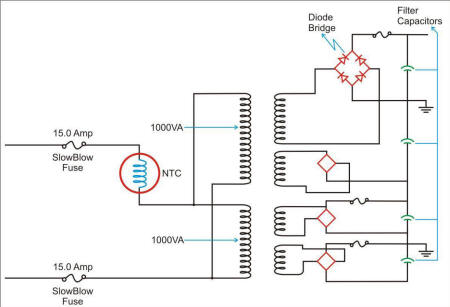
Each transformer rating: 1000 VA, transformer step-down: 30 V
Total transformer rating: 2000 VA
Filter capacitors used: 30V, 2300 μF
NTC Selection Criteria #1: Energy
Energy required for the NTC: Inductive reactance of the transformer

Note:
- Peak Inrush Current occurs in one cycle = 564 A, as measured on the oscilloscope
- Input Voltage = 120 VAC
- Frequency = 60 Hz

NTC Selection Criteria #2: Steady State Current
Assume, Efficiency of transformer: 70%, Ambient Temperature: 75ºC, Minimum input voltage: 90 V


Normally thermistors are rated up to 65ºC for their operating current, and then a de-rating factor must be taken in to account.
Decision criteria: choose an NTC Thermistor that can provide at least the steady state current as calculated above:
Using the de-rating curve at 75ºC , use corresponding 90% of max rated steady state current,
= 0.90 X 36 A = 32.40 A
You can use any of the NTC Thermistors that are rated up to 36.0 A to meet your Steady State Current and Energy Requirements. See the charts for part numbers.
| Transformer Protection Guide – Typical Inrush Current Limiters for Select Transformers | |||||||||
| Transformer KVA |
Single phase Input Voltage Vac |
Continuous Current A |
Inrush Current A |
Impedence X (Ω) |
Inductance Xl (µH) |
F (HZ) |
Energy (J) |
Min R (Ω) |
Recommended Part |
| .50 | 120 | 4.16 | 104 | 1.63 | 4328 | 60 | 23.4 | 4.9 | SL12 10006 |
| 1.0 | 240 | 4.16 | 104 | 3.26 | 8642 | 60 | 46.7 | 9.78 | SL22 10008 |
| 2.0 | 240 | 8.33 | 208 | 1.63 | 4328 | 60 | 93.62 | 4.89 | SL32 10015 |
| 3.0 | 240 | 12.5 | 312 | 1.09 | 2881 | 60 | 140.6 | 3.26 | AS32 5R020 |
| 5.0 | 480 | 10.42 | 260 | 2.6 | 6913 | 60 | 234 | 7.83 | MS32 10015 |
| 10.0 | 480 | 20.83 | 521 | 1.3 | 3457 | 60 | 469 | 3.92 | 2x MS32 2R025 or 1x MS35 5R025 |
| Inrush Current Limiters for Transformer Applications – Try It Now – In Stock | ||||||||
| Part | UL | R | SSI Max |
Joules Max |
Voltage Max |
Digikey | Mouser | Farnell |
| SL12 10006 | Y | 10.0 | 6 | 40 | 240 | 570-1078-ND | 995-SL12-10006 | 72J6734 |
| SL22 10008 | Y | 10.0 | 8 | 90 | 240 | 570-1034-ND | 995-SL22-10008 | 72J6819 |
| SL32 10015 | Y | 10.0 | 15 | 150 | 240 | 570-1058-ND | 995-SL32-10015 | 72J6844 |
| AS32 5R020 | Y | 5.0 | 20 | 300 | 240 | 570-1106-ND | 995-AS32-5R020 | |
| MS32 10015 | Y | 10.0 | 15 | 250 | 480 | 570-1014-ND | 995-MS32-10015 | 9006052 |
| MS32 2R025 | Y | 2.0 | 25 | 300 | 480 | 570-1019-ND | 995-MS32-2R025 | 72J6622 |
| MS35 5R025 | N | 5.0 | 25 | 600 | 680 | 570-1029-ND | 72J6634 | |


