Improving Inrush Current Protection
By Mehdi Samii, Ametherm Inc.
Summary
Many applications today, including industrial machinery, power tools and other high current equipment, use limiting inrush current as a major design consideration to combat the problematic effects of inrush current. Inrush current occurs when a system powers on and experiences a spike in current. This current can be substantially higher than standard operating current. If not properly managed, it can reduce the effective operating life and impose damage to equipment. For example, inrush current could disable a cooling fan, eventually leading to total system failure.
Applications that are switched on and off quickly, such as welding equipment, present a particular concern for limiting inrush current. The limiting inrush current circuit must reset instantaneously during each power on to protect the system. This further complicates the management of inrush current.
Inrush Current Overview
During power on, a high inrush current can occur because the power supply’s link capacitor functions to dampen ripples in the output current. This capacitor acts like a short, causing an inrush of current. The inrush lasts until the capacitor is charged. Length of the inrush current depends upon the power supply and link capacitor.
The low internal resistance of the power supply aggravates this issue. Any resistance in the power supply introduces inefficiencies through heat. To minimize resistance, engineers typically use an inductive load. While this improves the overall operating efficiency of the power supply, the lack of resistance enables the inrush current to pass through to the main system when the power supply switches on.
Temporarily introducing a high resistance between the power supply and system at power on limits inrush current. The resistance switches out when the initial current surge at power on reaches completion.
NTC-based Limiting
For many systems, a negative temperature coefficient (NTC) thermistor can effectively limit inrush current. An NTC thermistor provides variable resistance based on its temperature. Placing an NTC thermistor between the power supply and system limits inrush current (see Figure 1). At first, the initial temperature of the NTC thermistor is low, providing high resistance. When the system is powered on, it energizes the NTC thermistor, causing the temperature to rise, and thus lowering resistance. As resistance drops to a low value, the current passes through without adversely affecting normal operation or power efficiency.
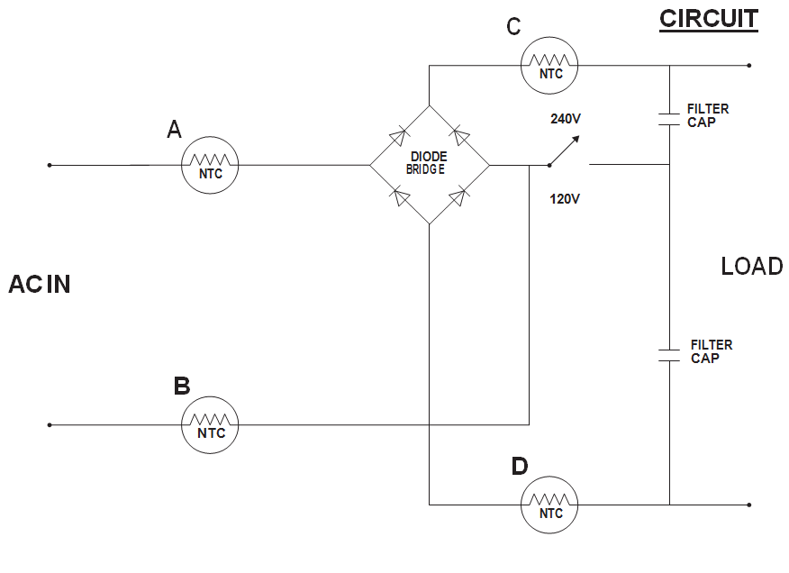
Inrush current limiters are typically installed in either locations A&B or C&D and depending on applications sometimes only on location A or C.
Figure 1:
NTC-based limiting circuit
To limit inrush current, an NTC thermistor is placed between the power supply and system (see Figure 1). Upon power on, the NTC thermistor provides high resistance to limit inrush current. As the inrush current drops, the NTC thermistor self-heats and its resistance drops to a low enough value to pass current through.
Find our thermistors at:


![]()
For example, consider a system with 10 A continuous current and an inrush current of 100 A. Upon power up, an NTC MS32 100 15 thermistor has an initial resistance of 10 ohms. Instead of passing 100 A, the NTC MS32 100 15 only allows 35 A to pass through. Then, as the NTC MS32 100 15 self-heats, its resistance drops and lowers the current until the inrush current is over. The NTC MS32 100 15 still continues to heat, dropping resistance to as low as 0.05 ohm where it reaches a steady state and passes current through minimum loss in efficiency.
NTC-based limiting has several advantages compared to a surge limiting circuit that uses a fixed resistor and bypass circuit. An NTC-based circuit typically occupies half the board space of a fixed resistor. It also has a very simple selection criteria to design in the circuit. Because resistance drops as it self-heats, no bypass circuit is needed to disable the limiting circuit. Finally, an NTC-based circuit has a lower total cost compared to limiting based on a fixed resistor.
PTC-based Limiting
NTC thermistors are the most commonly used limiter. They have a wide range of uses and applications. However, a few scenarios exist that require a positive temperature coefficient (PTC). If a system meets one of the exceptions listed below, a PTC thermistor is the best choice.
Exceptions
- Ambient temperature is greater than room temperature: If the ambient temperature is already high, the resistance of the NTC thermistor will be lower when the system is powered on. This lower resistance will reduce the limiting capabilities of the NTC thermistor and could put the system at risk.
- Ambient temperature is less than room temperature: If the ambient temperature is already low, the resistance of the NTC thermistor will be very high. The high resistance could limit all of the current and prevent the system from actually turning on, even after the initial inrush ends.
- Reset time needs to be near-zero: Certain types of equipment, such as welding gear or a plasma cutter, switch on and off frequently as part of their normal operation. This creates multiple instances of inrush current. NTC-based limiting operates on the nature of the NTC thermistor to self-heat and lower its resistance. However, when a system is quickly turned off and then on again, the NTC thermistor may not have completely cooled. It takes time for the NTC thermistor to release its heat and reset, dependent upon the size and mass of the NTC thermistor. If the NTC thermistor has not had sufficient time to cool, it will have a lower resistance when the system is turned on again, reducing its ability to handle the inrush current and protect the system.
- Short circuit: A short circuit drops the internal resistance of a system to near zero, quickly raising the current the system draws from the power supply. As the NTC thermistor limits this current, it quickly increases in temperature, thus lowering its resistance. This allows more of the current to flow through until it can damage the system. High current from a short can also destroy the NTC thermistor.
PTC-based Limiting Analysis
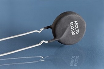
When the previous scenarios occur, a positive temperature coefficient (PTC) thermistor can provide effective inrush current protection. A PTC thermistor functions opposite to an NTC thermistor: as temperature rises, its resistance increases. Resistance begins to increase rapidly at Curie temperature (Tc). For example, Figure 2 shows the behavior of a PTC MCL20 500 100 thermistor compared to an NTC thermistor. At Tc resistance increases rapidly. At low temperatures resistance stays constant.
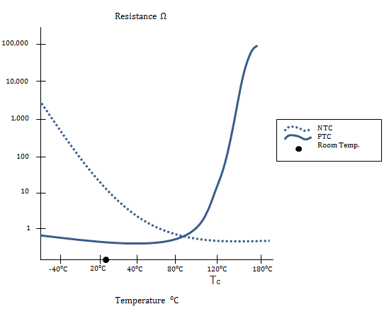
Figure 2:
Resistance for an NTCthermistor drops as it self-heats while resistance increase for a PTC MCL20 500 100 thermistor. At a specific threshold, 120° C for the PTC MCL20 500 100, resistance increases sharply, enabling the PTC MCL20 500 100 to respond quickly to inrush current. Also note how the PTC MCL20 500 100 has a flat response at low temperatures, making it effective across the entire temperature spectrum.
PTC Thermistor Tradeoffs
There are a few tradeoffs when designing in a PTC-based limiting circuit. A PTC thermistor costs about 1.5 times more than an NTC thermistor. Additionally, PTC-based limiting requires an active circuit to bypass the PTC thermistor to prevent shutting the entire system down. As resistance increases, it limits the incoming current. This occurs even after the inrush current has dropped to normal levels.
A bypass circuit is active during power on for a set interval, typically 3 or 4 times the amount it takes for the inrush current to settle (see Figure 3). Then, the bypass circuit shuts itself off and sends current back through the PTC thermistor to protect the system against shorts. If the bypass circuit were always triggered by a high current, the limiting circuit would not provide protection during a short. Overall, the increased responsiveness and advanced protection outweigh the added complexity and cost of a bypass circuit.
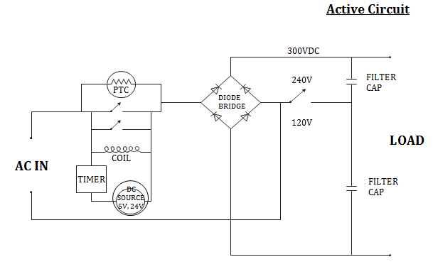
Figure 3:
Complete PTC-based limiting circuit, with bypass circuit
A PTC-based limiting circuit requires a bypass circuit to send current back through the PTC thermistor to protect the system against shorts. By setting the bypass to 3 or 4 times the amount it takes for the inrush current to settle, response time for the PTC-based limiter is extremely fast.
Conclusion
NTC thermistors limit inrush current by providing series resistance at the moment the device is powered on. They are also the most commonly used thermistor because they fit a wide range of equipment. Certain scenarios, however, may require PTC thermistors. These thermistors stop inrush current by providing high resistance in high temperatures. Examples include industrial equipment, power tools, and other fast switching systems (see Table 1). For these cases, PTC thermistors provide cost-effective protection and superior responsiveness. Other benefits include: near-zero reset time, ability to operate in extreme temperature conditions, and effectiveness when limiting high current from shorts.
NTC vs. PTC Comparison Table
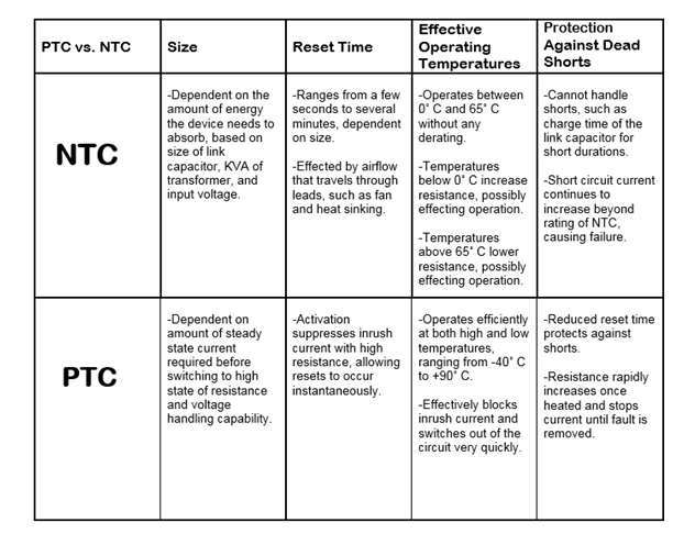
Table 1:
PTC-based inrush current limiting provides many advantages over fixed- or NTC-based limiting for applications such as fast switching and high current industrial equipment and power tools.
References:
Special Thermistors Limit Inrush Current:
https://www.ametherm.com/inrush-current/inrush-current-limiters-pcim/
How to Stop Inrush Current:
https://www.ametherm.com/inrush-current/how-to-stop-inrush-current/
Ametherm Thermistor Data Sheet:


