An Inrush Current Limiter (ICL) can protect electrical equipment from overheating when switched on because of inrush current. And, because inrush current equals the maximum instantaneous surge of incoming current from a power source, it can be as much as 2 to 3 times the steady state current of the attached device. Inrush Current Calculators are the best way to measure the resistance versus temperature curve to get the right Inrush Current Limiter.
Switching power supplies, DC motors, and lighting ballasts can develop extremely high peak inrush current at turn-on unless you implement inrush current protection. Additionally, magnetic devices that produce alternating current such as electric motors or transformers can draw as much as 30 times their steady state current at switch-on.
Without protection from inrush current, the only limits to the amount of inrush current drawn are the line impedance and the equivalent series resistance of a capacitor. Based on these facts, one would think that because today’s circuit systems run more efficiently and maintain lower impedance, inrush current would not be an issue. Unfortunately, that is not the case.
In fact, the overall efficiency of low impedance also contributes to high inrush current, increasing the possibility of equipment overheating during start-up. Using inrush current limiters will help ensure that systems do not overheat due to inrush current. On our website, you can view our full line of inrush current limiters and learn how to reduce inrush current.
How do I Select the Right Inrush Current Limiter for My Application?
Inrush current limiters are designed with different characteristics like resistance versus temperature curve to accommodate numerous applications. Because of this, it is necessary to make some calculations based on your system requirements to select the best inrush current limiter for your needs.
At a minimum, you will need to know:
- Maximum Output Power: Based on specific system or design requirements, this is a variable and is relevant to the steady state current of the application
- Input Voltage: This is the available incoming line voltage to the application in question. For example, 110 or 120 VAC
You should also be aware of the following information:
- Reset Time: How often the system will be switched on/off during a given time frame
- Single Phase or Three Phase: Incoming voltage pulled in from either a single line or three lines
- Filter or Link Capacitor Value: Value in Micro Farads. Quantifies the magnitude of capacitance
- Scope Trace of Inrush Current: A snapshot of inrush current at a moment in time
- Fuse or Circuit Breaker Rating if applicable
- Inrush Current Rating of Diode Bridge if applicable
Example Problem Statement
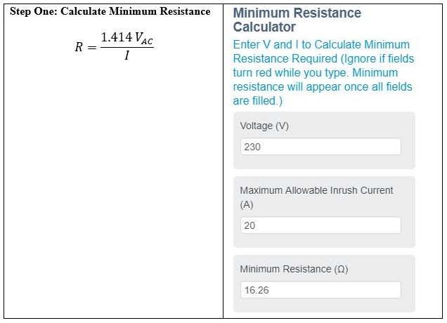
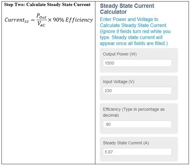
Current Situation: A 1500-watt switch mode power supply trips a 20-amp breaker at turn-on due to high inrush current. How do you stop the breaker from tripping?
Given Information:
- 230 VAC input voltage
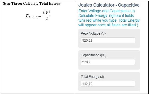
- Peak Voltage = 230 VAC * 1.414 = 325.22 V
- Filter capacitance of 2700μF
- 90% Efficiency
Solution: You should add an Inrush Current Limiter to reduce high inrush current at turn-on which should stop the breaker from tripping due to the high inrush current.
 How to Use Our Inrush Current Calculators
The above calculations recommend Inrush Current Limiter MS32 20008
- 20 ohms
- 250J
- 8 amp-continuous
What if Capacitance or Scope Trace are Not Available
How to find the Total Energy
Even if your missing capacitance and, or scope trace, you still need to determine the total energy to select the right Inrush Current Limiter. Should this be the case, outlined below is a formula you can use as a “Worst Case Scenario” alternative to estimate the total energy requirements.
Use the following assumptions:
- If filter capacitor is not available, then assume the duration of inrush to be one (1) cycle, and that one cycle equals 60 Hz which translates to 0.0167 seconds.
- If scope trace is not available, assume that inrush current is 30 x the steady state current.
The formula would look like this.
Energy = 30 x Steady State Current x 0.0167 x input voltage
Visit Wikipedia for more information on inrush current, its causes, cures, and prevention.
For easy access, you can use our Inrush Current Calculators here or you can calculate inrush current on our website