
Written By Joe Conti
NTC thermistors are a great way to control the power functions of a residential furnace system. These thermistors can sense the air temperature in the furnace heating chamber and turn the power on and off. Replacing the power control of the furnace with a temperature sensor is easy to do. This article will walk you through how to do this starting with an Arduino microcontroller and an NTC thermistor.
 The application for this design will be a central air heating system (furnace) for residential use. The furnace is controlled by a thermostat as well as a fan and limit control installed in the air heating chamber leading to the warm air duct distribution system.
In using this design, the goal is to replace the controller currently being used, which is a White Rodgers 5D51-90 fan and limit control inserted 8” into the heat chamber. The 5D51-90 fan and limit control is made up of two bimetallic switches, a limit switch, and a blower switch.
The design for the new controller uses a negative temperature coefficient (NTC) thermistor that senses air temperature in the heating chamber. The NTC thermistor’s resistance value is determined by a microcontroller, which in turn determines when to operate electrical relays that provide the fan and limit switching functions.
The microcontroller being used is an Arduino Nano Series that provides an analog input channel to read the voltage produced by the NTC thermistor circuitry. The Arduino Nano Series also will provide two digital outputs that operate the electrical relays circuitry. [See Appendix Page A8 at the end of this article for Arduino Nano Series circuit diagram]
Application Design Parameters
NTC Thermistor
Ametherm PANW103395-353 NTC Thermistor [See Appendix Pages A4 and A5 for data sheet]
Fan and Limit Controller Design
The NTC thermistor circuitry for the new controller is made up of a constant current sink that provides a constant 100 micro amp excitation current through the NTC thermistor along the temperature measurement range. A small constant current is desired to minimize the self-heating effects of the NTC thermistor. The constant current components are located on a circuit board with the microcontroller and two LEDs that indicate the energized state of the relays. [See Appendix Page A1 for the constant circuit sink diagram]
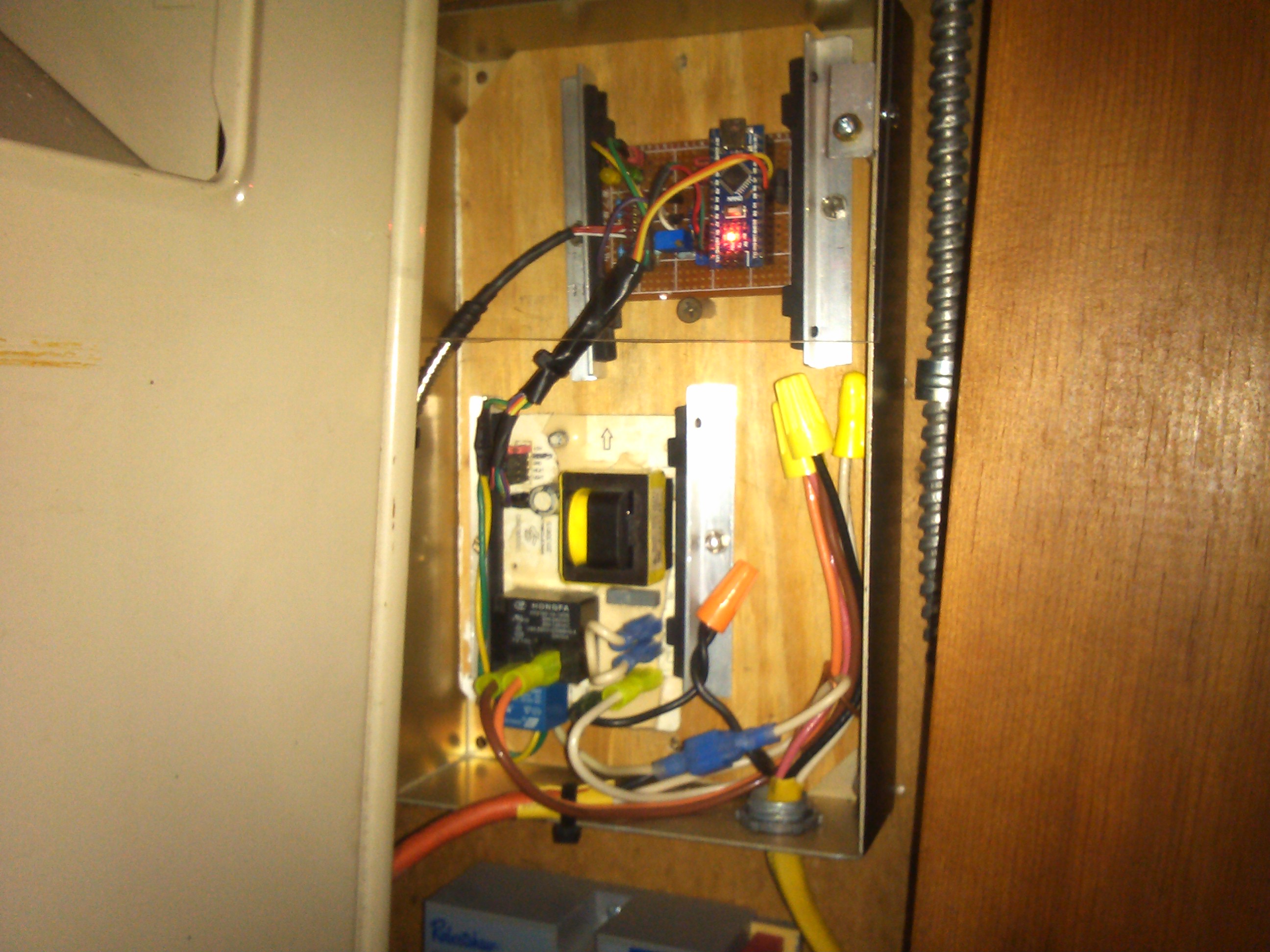
A second circuit board with two sides is composed of a 120VAC to 12VAC stepdown transformer with:
- AC to DC rectification components
- A limit relay
- A blower relay
- A 5VDC voltage regulator
- Transistor circuitry to interface the relays to the microcontroller
The transformer, relays, and I/O pin header are mounted on the top side of the circuit board. The rectification components, transistors, resistors, and the 5-Volt regulator are located on the bottom side of the circuit board. The transformer circuitry provides 12VDC power for both the relays and a regulate d 5 volts for the microcontroller board. [See Appendix Page A2 for a circuit diagram for these components]
Limit Switch
The limit switch controls the maximum heating chamber temperature and is normally closed. However, it opens at a high temperature of 200 ºF (93 ºC) and closes at 160 ºF (71 ºC). The limit 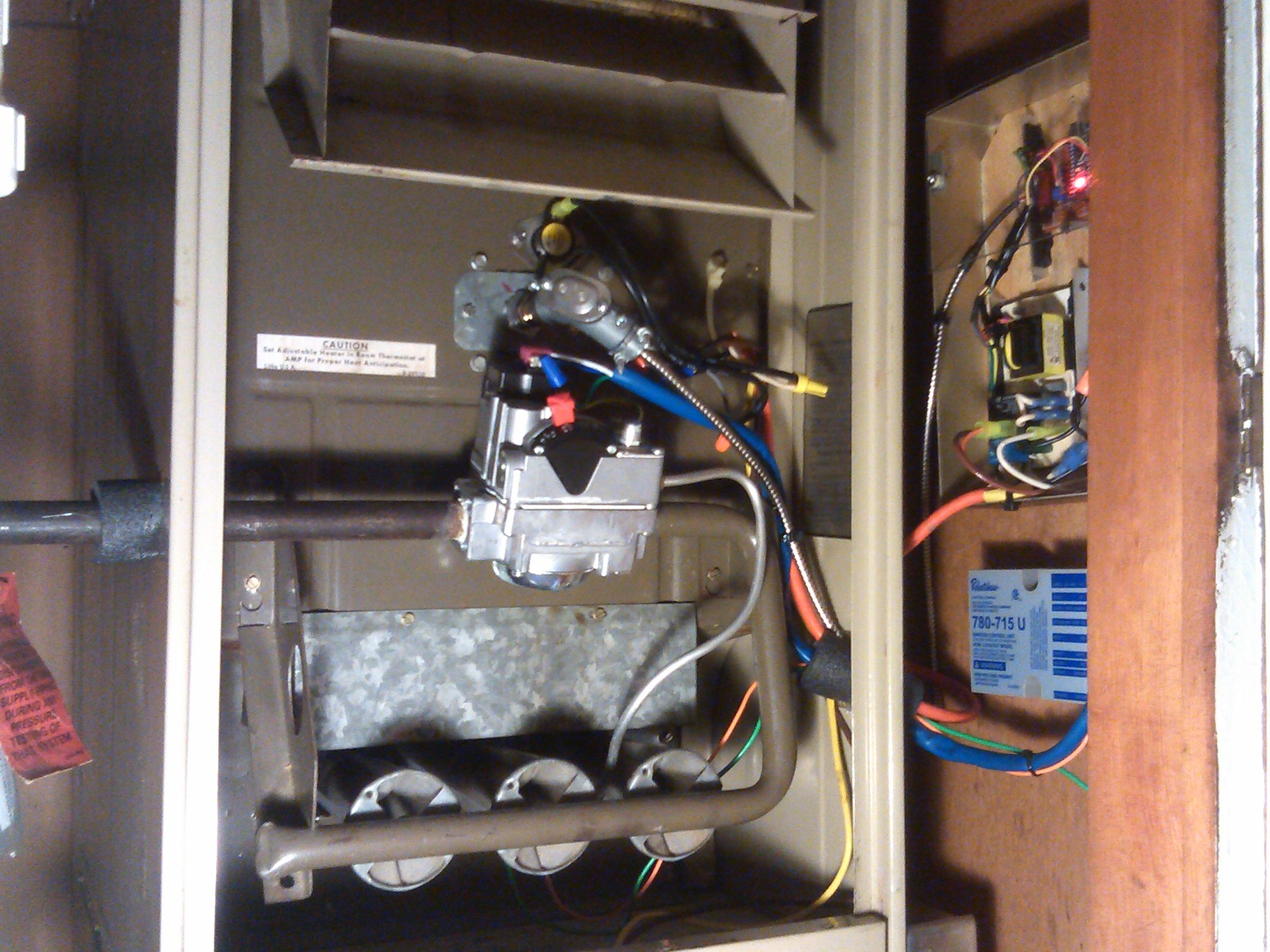 switch passes the 24VAC call for heat signal from the thermostat to open the gas valve and lights the burners to begin heating the air.
Blower Switch
The blower switch operates the 120VAC blower fan and is normally open. However, it closes at 100 ºF (38 ºC), allowing the blower fan to deliver warm air until the thermostat demand is satisfied. At that point the thermostat shuts off the gas valve and the blower fan continues to run until the blower switch opens at 70 ºF (21 ºC) turning off the blower fan.
Warmed Air Heating Range
60 ºF (16 ºC) to 200 ºF (93 ºC) sensed by a 10K Ω NTC thermistor temperature sensor with beta of 3950 inserted 8” into the heat chamber. The microcontroller and related electrical hardware will be located on the external side of the heating chamber at approximately room temperature.
Fail-Safe Device
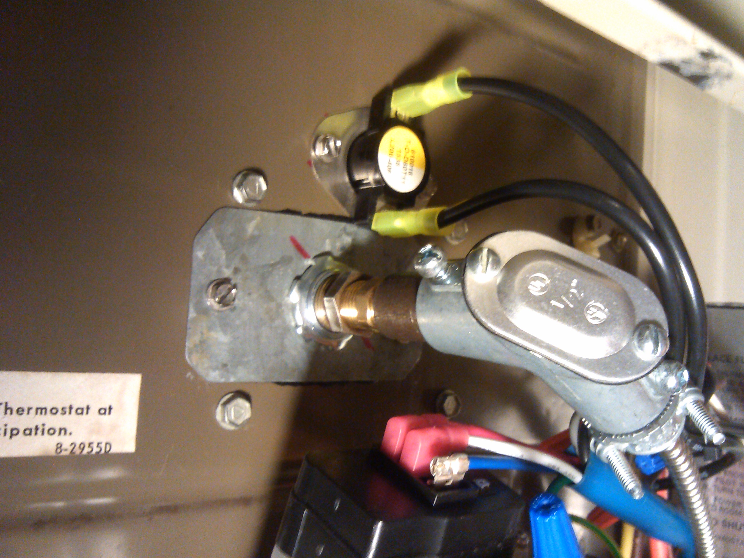
The final component of the application design used in case a malfunction arises with the fan and limit controller is a SUPCO L200-40F bimetallic high limit switch placed in series with the limit relay contact. The fail-safe is in the heat chamber along with the NTC Thermistor temperature sensor probe (PANW103395-353), and is normally a closed contact that opens with a temperature rise to 200 ºF (93 ºC) and closes with a temperature drop to 160 ºF (71 ºC). [See Appendix A3 for gas valve and blower motor diagram]
Software Mathematical Strategy
A spread sheet analysis of the thermistor data sheet information and Steinhart-Hart
Steinhart-Hart equations were performed to compare data sheet values with temperature, resistor, and Beta values derived from the equations. The data sheet values and Steinhart-Hart calculated values were graphed to see how well they compare. The Steinhart-Hart calculated values fit very nicely to the data sheet values.
Since the NTC thermistor resistance infers the measured temperature, all that is necessary in software calculations is to derive the NTC thermistor resistance and compare that measured resistance value to selected data sheet resistance values, allowing the microcontroller to control the process (i.e. open and close the limit switch and turn on/off the blower switch). Four data sheet resistance values will be used and are assigned to floating point constant variables.
The measured value of an NTC thermistor resistance is derived using the following equation:
Rthermistor = [(1023 VA1)Bit∗((Vs/100µAmp)/1023Bit)]Ω
- 1023: References the full scale digital value of the microcontroller A/D converter
- VA1: The digital voltage input from the NTC thermistor constant current circuit
- Vs: The full scale measured analog voltage value to the constant current circuit
- 100µAmp: The calibrated excitation current in that circuit
A conversion constant derived from the ratio of precise measurement of Vs and precise adjustment of the excitation current divided by 1023 has the dimensions of Ohms per bit. That conversion constant is then assigned to a floating point constant variable. Both precise values are measured when the constant current circuit is calibrated.
Here are a couple examples:
Vs=5.000 and excitation current =100.00 µAmp then the conversion constant is [(5.000/100.00e-6)/1023]=48.8758 Ohm/bit.
If the VA1 digital voltage is read as 701 then the thermistor resistance is calculated as follows:
Rthermistor=float(1023-701)*48.8758 =15,738.03 Ohms
This value is accurate at most to (48.8758/2) Ohms = ±0.5 LSB according to the Atmel data sheet and infers a temperature close to 59 ºF (15 ºC ± 0.5 °C).
Suppose VA1 digital voltage is read as 1006 then Rthermistor = 830.89 Ohms, which infers a temperature close to 201.2 ºF (94 ºC ± 1.°C). [See Appendix for a spreadsheet and graph that compares the calculated resistance versus data sheet resistance]
The microcontroller compares the calculated resistance to the selected Ametherm data sheet resistance values and determines the appropriate action to take.
Software Implementation
The Arduino IDE software was used to develop a sketch program for the fan and limit control microcontroller. [See Appendix Pages A11 – A14 for sketch] Also, the program is included on the DVD disk along with an additional program used for calibration of the constant current sink.
 Conclusion
The electronic circuitry was constructed, the software program was written, and the fan and limit controller was bench-tested to verify its operation for the intended application. [See Appendix Pages A15 – A22 for annotated pictures of the project]
 Conclusion
Final activities to complete the project include:
- Fabricating the NTC thermistor probe mounting flange
- Mounting both the NTC thermistor probe and high-limit switch to the heat chamber
- Fabricating an enclosure for the circuit boards
- Installing the components and interconnecting wiring to the furnace
The success of this design is due in large part to the Ametherm NTC thermistor probe accuracy and quality. The operation and description of the design has been described and documentation supporting the development can be found in the Appendix.
Joe Conti is a retired electrical engineer with more than 20 years of experience in industrial markets for a multitude of businesses in Tulsa, Okla. He is graduate B.S.E.E. from Oklahoma State University with an emphasis in electrical power and controls.

