Protect An Inverter From Inrush Current
By: Mehdi Samii
Kaushik Das
Inverters
Inverters are electrical systems that provide variable voltage (AC output) when connected to a DC input source. Inverters are available in two varieties: three phase and single phase. These inverters are also known as static frequency battery chargers or variable frequency drives.
Inrush Current in Inverters
A common failure of inverters is overloading the inverter due to inrush current. This is due to the fact that most inverters are designed with a minimum amount of resistance to increase their efficiency and minimize losses due to heat.
| Inverter Component | Cause of Failure |
|---|---|
| Failure of electrolytic capacitors | Current and voltage stress |
| Welding of contactors | Inrush current |
| Failure of Bridge rectifiers | Inrush currents greater than the rating specified |
Cause of Inrush Current Failure :
An overload condition will occur even if you switch on three appliances–one by one–connected to an inverter.
Consider the following:
- A 1000W inverter (more specifically, a 1500W inverter with 50% total overload capacity)
- Three standard appliances, such as a refrigerator of 300W, an LCD Television of 300W, and a computer of 300W. Total load for these appliances: 900W.
- A 1000W inverter is fully capable of running the above three appliances
The overload condition happens because of energy required for start-up. But, the start-up or inrush current for each appliance could be as high as 900W or 3 times the rated power.
The inverter overloads in the following scenario:
- Step 1: If we switch on the first appliance, the load is 900W which is less than the rated capacity of the inverter. Thus, no overload situation is encountered
- Step 2: If you switch the second appliance, the total wattage needed is as follows: First appliance 300W + second appliance 900W = 1200W. No overload situation is encountered.
- Step 3: If you switch the third appliance, the total wattage needed as follows:
1st appliance 300W + 2nd appliance 300W + 3rd appliance 900W = 1500W
Notice that an overload condition is encountered as soon as the third appliance is switched on to the inverter.
See (a) of Figure 1 below.
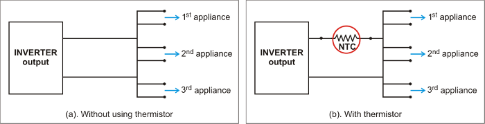
Figure 1
Solution – Inrush Current Limiter
Use an Inrush Current Limiting Thermistor (See Figure 1(b).) to address the overload scenario of the sample problem:
- As per Step 3 above, the inverter wattage needed including the overload condition > 1500W
- Since max output power allowed is 1000W
- Allowed current: 8.0A, 50 # 2 at 120V
- Normal continuous current per appliance = 300W/120V = 2.50A
- Due to inrush current = 2.50A x 3 = 7.50A
- Duration of inrush = one cycle = 1 x 1/50 sec = 0.02 sec
- Energy of the thermistor = 120V x 7.50A 0.02 sec = 18.0 J
- Note: The energy requirement, mentioned above, is needed to handle without self destruction.
- So, for three appliances that start up at the same time, we need 3.0 x 18.0 J = 54 J
- Minimum resistance: 120 V x 1.414/8.0A = 21.21Ω
(This ensures that the current does not exceed 8.0 A.) - So if we assume Ambient of 50°C, Min Resistance = 40Ω, so we can reconnect
Ametherm suggests two methods for solving the inrush current problem:
Method (a)
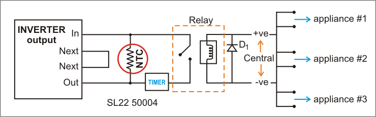
Figure 2
In the above circuit (Figure 2),
- NTC = SL 22S0004 (50 Ω, 4.0 Amp, 75 Joules), UL (E204153), CSA (CA40663) is used to bypass the surge after one second.
- Note that the NTC Inrush Current Limiter does not interfere with the efficiency of the inverter since the relay is also protected from the inrush current by the thermistor. The thermistor will conduct through the relay with 99.2% efficiency loss of current.
Method (b)
As shown in Figure 3, choose Ametherm P/N: MS3220008 x 2 to provide 40Ω, 10 AMP, 500 Joules.
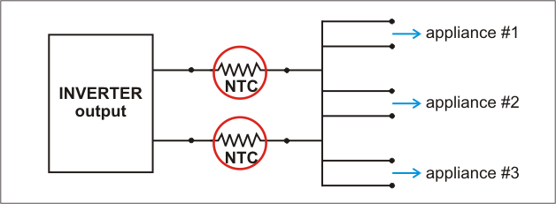
Figure 3
- Efficiency C 8.0 A = I2R = 14.1 W losses due to thermistor
- RC 8.0 Amp = 0.22
- Efficiency = 985.90/1000W = 98.6%
Conclusion: method (b) is more cost effective
Inverter Circuits with Thermistors
Simple NTC thermistors are shown below in the following three circuits: Figure 4, 5 and Figure 6.
These thermistors minimize the effect of inrush current on components, such as bridge or link capacitors.
Schematic – Classic Inverter Circuits With NTC Inrush Current Limiters
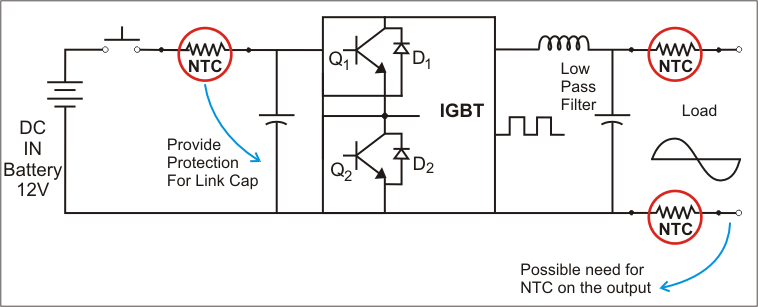
Figure 4
Schematic – Frequency Charger With Inrush Current Limiters
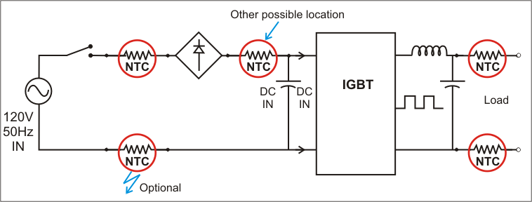
Figure 5
Schematic – Variable Frequency Drive
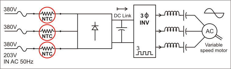
Figure 6
References
- Elliot Sound Products
- Sinetech Advanced Power Products
- Rockwell Automation Publication PFLEX_A700lk_EN_P Sept 2011
- US Patent 2003/0150369A1


