When a battery is connected to a load with capacitive input, there is an inrush current surge as the capacitance is charging to the battery voltage.The input current depends on the input capacitance; the larger the batteries and the more powerful the load, the larger the input capacitance. A large inrush current (in the precharge circuit, without protection) can cause the following:
- Damage to input filter capacitors
- Blowing of the main fuse if it is carrying the inrush current without protection
- Contact failure (and reduction in current carrying capacity) due to arcing and pitting from high inrush current Damage to the battery cell, which is not rated for inrush current
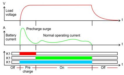
Below is a typical precharge circuitry for battery operation and timing diagram, showing how the circuit operates. (Courtesy of Lithium -ION BMS)
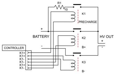
In its most basic form, the precharge circuit operates as follows:
- OFF: When the system is OFF all relays / contactors are off.
- Precharge: When the system is first turned on, K1 and K3 are turned on to precharge the load, until the inrush current has subsided. R1 shows the location of the thermistor in the precharge circuit.
- ON: After precharge, contactor K2 is turned on (relay K1, must be off to save coil power).
For this application note, we will focus on the selection of the thermistor.
Selection of the Thermistor
The minimum resistance of the thermistor is determined by the following:
- Ambient temperature
- Input capacitance value (of the precharge circuit)
- Battery voltage
The precharge surge current reaches 63.2% (1/ e) of its initial value after a time τ = RC.
In the selection of the thermistor, we consider a time value of “five time-constant” when the capacitances are fully charged and the surge current reaches the normal operating current.
For the this design, we will assume the following quantitative values:
- 20 milliseconds
- Ambient operating temperature: Varies between 10°C to 50°C
- Battery voltage: 100 volts
- Capacitor bank: 50,000 μF
5τ = RC
R = 5τ / C = 5 (0.02 sec) / 0.05F = 2.0 Ω.
Looking at the at R-T curves for the Ametherm thermistor at an ambient of 50°C, the material “C” exhibits
R @ 50°C/ R @ 25°C = 0.412 @ R @ 10°C / R @ 25°C = 1.70
Therefore, minimum resistance @ 25°C = 2.0 / 0.454 = 4.40Ω, so our standard part has 5.0 ohm nominal resistance
At 10°C, the standard part will have a resistance of 5.0 Ω x 1.70 = 8.50 Ω, which will meet our minimum resistance.
To determine the energy the thermistor needs to handle without self-destruction,
E = ½ C V2 = ½ (0.05) (100) 2 = 250 Joules
The steady state current is not calculated, because in most precharge circuits the steady state current goes through the contactor. The part that would meet your specification is AS32 5R020.
Key benefits of Ametherm AS Inrush Current Limiters
- Lower current density (as compared to traditional types of inrush current limiters)
- Faster reset time
- No hot spots from fatigue, because of lower current density and uniform temperature gradient throughout the disc
- Wider temperature range of operation with out de-rating

