Reducing Inrush Current to Capacitors
Calculating the amount of current flowing to a capacitor, then protecting your load from this initial flow of current is important for any electronic device. The ability to reduce this inrush, caused at powerup, can typically be accomplished by the use of an NTC (negative temperature coefficient) thermistor inrush current limiter.
Cause of the Inrush Current
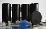
Filter capacitors are devices designed to reduce the effect of ripples when AC waveforms are converted to DC waveforms. In a typical power supply, the AC current flows through the diode bridge rectifier, converting the voltage to DC, then flows into the filter capacitor. At power on, an inrush of current occurs and while in its charging phase the filter capacitor acts like a dead short. This state continues until the filter capacitor is completely charged, leaving the potential of the inrush current to fully hit the load.
Inrush Current Protection
Safeguarding against the filter capacitor’s charging period’s initial current inrush flow is crucial for the performance of your device. Temporarily introducing high resistance between the input power and rectifier can increase the resistance of the powerup, leading to reduction of the inrush current. Using an inrush current limiter for this purpose helps because it can provide the initial resistance needed.
Placement of Inrush Current Limiter
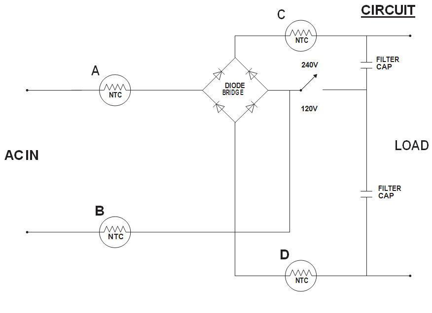
The diagram below illustrates a typical set up of a circuit, with power entering at “AC IN” and the filter capacitors located at the “FILTER CAP.”
To limit the onset inrush current, an NTC thermistor inrush current limiter is placed IN SERIES with input power at “A,” or “B,” or optionally in-series after diode bridge at “C,” or “D.” This allows the filter capacitor time to charge without the inrush current fully hitting the load.
Inrush Current Limiter Proving Resistance
The placement of an inrush current limiter between the input power and load, demonstrated in the diagram, gives the inrush current limiter the ability to provide resistance. When energized, the inrush current limiter self-heats and causes its body temperature to rise. This then leads the inrush current limiter to lower its resistance. As the resistance drops to a low value, the current can pass through at a standard level, without adversely affecting the normal operation or power efficiency. By the time resistance reaches the circuit’s steady-state condition, the filter capacitor will be fully charged and ready to deliver DC power to the load. At this time, the inrush current limiter will remain at this steady-state condition, allowing the current to flow through unaffected.
Inrush Current Limiter Selection
Choosing the right type of NTC thermistor inrush current limiter for your inrush current limiting needs can be vital when working with filter capacitors.
To select the right inrush current limiter there are a few measurements* you will need:
- Zero power resistance (R@ 25ºC)
- Energy measured in Joules
- Steady-state current
*There is one more variable you should keep in mind when choosing the right inrush current limiter, which is ambient temperature. The calculations/examples used in this article are based on the ambient temperature being between 0ºC and 65ºC. If your environment is outside this scope, you will want to refer to a derating chart to see how to modify your calculation to ensure the best productivity out your inrush current limiters.
Most of the time you can get these measurements from the specifications provided by the manufacturer.
To calculate yourself see below or skip to the next section
Zero Power Resistance (Ω)
Peak Voltage/Max Allowable Inrush Current
Where:
Peak Voltage = (Vrms)(1.414)
Max Allowable Inrush Current = Fuse in power supply or breaker on AC line.
Example:
(120Vrms)(1.1414)/20A =
169.68Vp/20A =
8.4 Ω
Energy Measured in Joules (J)
½(Capacitance)(Peak Voltage)²
Where:
Capacitance = Will come from the specifications provided by the manufacturer
Peak Voltage = (Vrms)(1.414)
Example:
(0.5)(.0047F)(169.68)² =
67.6 J
Steady-state Current (A)
Will come from the specifications provided by the manufacturer
Can be formulated by:
Input Power/ Output Voltage (W/V = I)
Example:
Steady-state current given at 3A
Once you have the values for zero power resistance, energy measured in joules, and steady-state current, it’s time to translate them into the specifications needed to choose your NTC thermistor inrush current limiter.
First, you will need to go to the Inrush Current Limiter Full Line page to see a listing of NTC thermistor inrush current limiters Ametherm has available. (chart explanation is shown below)
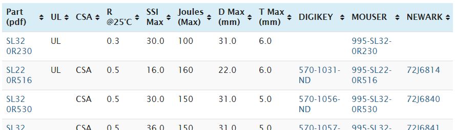
- The first column is the part number
- The second column is whether it is UL listed
- The third column is whether it is CSA compliant
- The fourth is the zero power resistance number (reference from your calculations)
- The fifth is the steady-state current number (reference from your calculations)
- The sixth is the maximum amount of energy measured in joules number (reference from your calculations)
You always want to round up the numbers when using this chart.
Taking the numbers from the above examples – 8.4Ω, 3A, 6.65 J – round this up to 9Ω, 3A, 7J
Reviewing the chart online, you will notice there are no R@ 25ºC = “9” values, but there are R@ 25ºC = “10”, going up from “8.4” to “10” is fine when selecting an NTC thermistor inrush current limiter.
From here, looking at your value for steady-state current, you will want a value of 3 or more.
Finally, for the energy measured in joules you will want a value of 7 or more.
With these the values established, the ideal inrush current limiter is SL10 10003.

Once you have located the correct product number, you can buy direct from any of Ametherm’s distributors or request a free sample.
![]()
![]()
![]()
Now that you have a greater understanding of filter capacitors in relation to inrush current, selecting the right NTC thermistor inrush current limiter for your existing and future projects should be a snap!
If questions arose, reach out to one of our engineers, and they will answer any questions you have about filter capacitors, NTC thermistor inrush current limiters or any other thermistor related queries.