We’ve made a discovery and wanted to share it with you; introducing the Arduino Uno. If you’re an electronics geek who’s been wanting to learn more about the vast community of “Hardware Hackers” out there, read on!
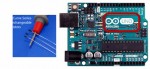
We discovered that you could hack together some awesome stuff with an Arduino Uno and other electrical components such as thermistor temperature sensors. And when you combine the Arduino and thermistors the possibilities are endless.
We give you an inside look as we show you how we hacked together a DIY temperature sensing device in no time. And, because we used an NTC thermistor temperature sensor, this device will provide greater accuracy. We’ve also discovered whether you’re new to electrical engineering or you’re a seasoned veteran; exploring the science and art of hardware hacking is an awesome adventure so join us!
Inside this post, we’ll spill the beans on the relationship between Arduino and Thermistors, and you’ll see how simple it is to build a DIY home thermostat using an Arduino and Thermistors. We show you how to set up and wire your Arduino, and we show you how to program the Arduino to get an accurate room temperature reading via an LCD display.
Our Project
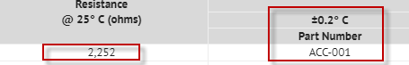
Our goal was to build a temperature sensing device using the Arduino Uno and an NTC thermistor temperature sensor that would display the same room temperature as a standard room thermometer. We were targeting a temperature range between 20 ˚C and 30 ˚C.We wanted a compact NTC thermistor temperature sensor with high accuracy for this project, so we chose the Ametherm ACCU-CURVE series part # ACC-001 which has an resistance value of 2,252 @ 25 ˚C.
Although there are several ways to read temperature using an Arduino, in this post, we focus on the use of NTC thermistor temperature sensors with the Arduino Uno for a few good reasons.
- First, the ACCU-CURVE series of NTC thermistor temperature sensors are interchangeable, which means no need to re-calibrate.
- They provide a high rate of accuracy and are compact.
- They respond quickly to temperature changes.
What is Arduino Uno?
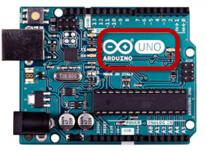 The Arduino Uno is an open-source electronic microcontroller platform that combines user-friendly hardware and software to create prototypes. The Arduino Uno board comes in the form of a kit that you can wire differently depending on your project specifications.
You have many choices in the type of microcontroller that you use, but for this project, we found the Arduino Uno offered us endless impossibilities. It’s a versatile tool and an excellent choice for prototyping projects.
What Does It Do?
Arduino boards can read input data then turn it into the desired output using the IDE software. You can control what your board does by uploading a set of instructions from the IDE to the microcontroller on the Arduino board. Visit Arduino.org for more information.
Why Combine Arduino and Thermistors?
For this project, the Arduino and thermistors work together as a temperature sensing device in a precise and logical manner to provide reliable and accurate temperature readings. To illustrate this productive relationship, we take you on a journey from wiring and programming the Arduino, to viewing the room temperature results on the LCD.
What we’ll Cover
- NTC thermistor selection and calculations
- How to setup and wire your Arduino Uno Temperature Sensor device
- How to program your Arduino Uno based on your requirements
- How to upload the necessary code to the IDE computer application then download the output to the Arduino
- How to verify your results
- Troubleshoot issues
What you’ll Need
- Arduino Uno Kit. (Kit includes a USB cable and hookup wire)
- Computer with Arduino IDE software installed. Visit http://www.arduino.org/downloads to download the free software
- An NTC Thermistor Temperature Sensor (We’ll walk you through the selection process for this project.)
- A variable resistor
- Mounting Board
- Multimeter
NTC Thermistor Selection Process
Because we were looking for the most accurate temperature reading between a range of 20 ˚C and 30 ˚C, we chose the ACC-001 from Ametherm’s line of ACCU-CURVE Precision Interchangeable thermistor temperature sensors. This series of NTC thermistors carries a high accuracy rating of ±.2 °C making them an excellent choice for our project.
To see how we chose the ACCU-CURVE-001, you can navigate to our ACCU-CURVE page on our website to view the table as shown below. To stay within our desired temperature range, we’ve highlighted the three resistance values that we needed to calculate the Steinhart-Hart coefficients.
Click the table to visit our ACCU-CURVE page.
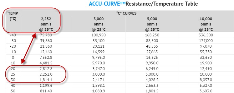

If you need a different resistance value, you would still use this same process to select the right NTC thermistor temperature sensor. However, you would apply the required resistance value. Next up; we introduce you to the Steinhart-Hart model of calculating the temperature coefficient using the resistance values you have selected.
Doing the Math
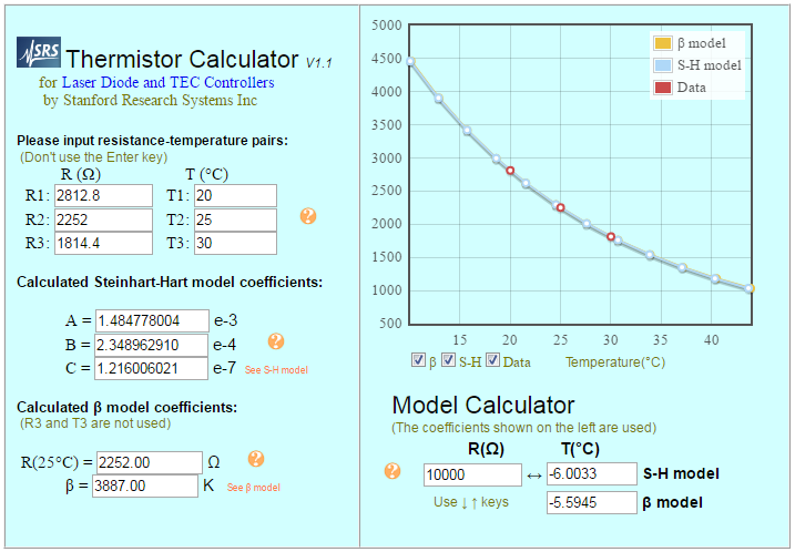
Once you’ve determined the desired R/T values from the ACC table above, using the Steinhart-Hart model; enter them into a thermistor calculator like the one shown here to determine the A, B, & C coefficients as shown below. Additional accuracy information is available if you hover over the yellow question marks.
In this example, we used the SRS thermistor calculator provided by Stanford Research Systems.
Click the calculator to view a working version of the calculator.
We have a dedicated Steinhart & Hart calculator on our website for your use as well.
Visit Ametherm’s NTC Thermistors Steinhart & Hart page to use our Steinhart & Hart Temperature Coefficient Calculator and get more information on the Steinhart-Hart Equation with examples.
Setting Up Your Arduino Uno Temperature Sensor Unit using our NTC ACCU-CURVE-001
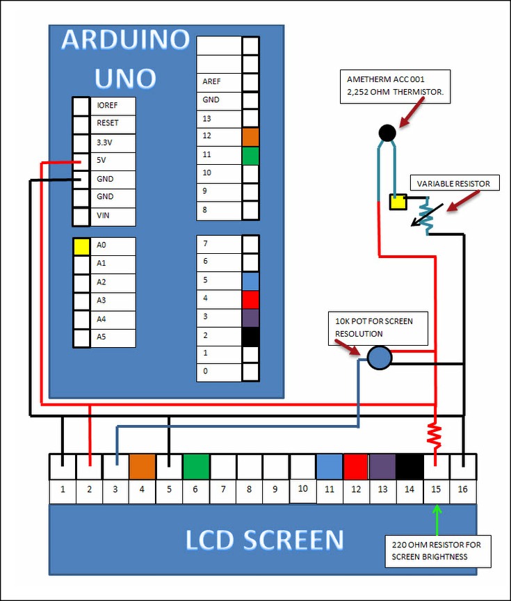
Setup begins with connecting the wires. We used a junction box for simple wire coupling. Then, following the diagram; connect the color-coded wires to the matching color-coded pins on the board.
Pay close attention to the variable resistor requirement notes on the left as to avoid any errors due to a mismatched NTC thermistor temperature sensor and the variable resistor.
Variable Resistor Requirements
The resistance of the NTC thermistor temperature and variable resistor used in this project must have the same ohm value.
Thus, if the NTC thermistor reads 2,252 ohms @ 25 ˚C, the variable resistor must read 2,252 ohms. Dial the variable resistor to exactly 2,252 ohm’s for best accuracy.
Calibrating the variable resistor
Before you install the variable resistor on the Arduino, you’ll need to calibrate it so that it has the same ohm’s value as the NTC thermistor temperature sensor.
You do this by connecting a multimeter to the to the uninstalled variable resistor then adjust the differential knob on the variable resistor until it matches the resistance of the NTC thermistor temperature sensor.
When you have completed the calibration process, disconnect the multimeter from the variable resistor and continue installing the variable resistor as shown in the diagram.
We do not recommend that you calibrate the variable resistor after you have installed it. Doing so will cause an inaccurate reading.
____________________________________________________________________________________________________________
You can power the Arduino in one of two ways:
- If you need it hardwired, connect the USB directly to your computer
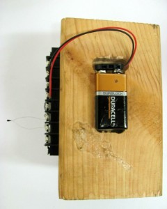
- If you need mobility, you can install and use a 9-volt battery
NOTE: If you power the Arduino with the 9-volt battery; connect the red (+) positive wire to the VIN pin on the board and connect the black (-) negative wire to the GND pin on the board.
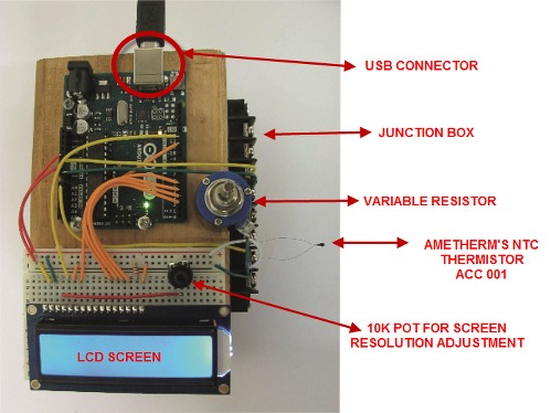
Assembled Arduino connected via USB Connected via 9-volt battery
Programming Your Arduino Uno Thermistor Temperature Sensor Unit
You program the Arduino with the aid of the IDE software on your computer. The IDE does require some C++ programming code, so we’ve included the code for you to copy and use if you decide to build a temperature sensing device as we have demonstrated here. We recommend that you save the code to your computer for future use.
Select and copy the code you see between the blue lines below and paste it into the IDE Compiler.
#include <LiquidCrystal.h>

int ThermistorPin = 0;
int Vo;
float R1 = 2252;
float logR2, R2, T;
float A = 1.484778004e-03, B = 2.348962910e-04, C = 1.006037158e-07;  // Steinhart-Hart and Hart Coefficients

LiquidCrystal lcd(12, 11, 5, 4, 3, 2);

void setup() {
Serial.begin(9600);

}

void loop() {

Vo = analogRead(ThermistorPin);
R2 = R1* (1023.0 / (float)Vo - 1.0);
logR2 = log(R2);
T = (1.0 / (A + B*logR2 + C*logR2*logR2*logR2));  // Steinhart and Hart Equation. T  = 1 / {A + B[ln(R)] + C[ln(R)]^3}
T =  T - 273.15;

lcd.print("TEMP = ");
lcd.print(T);
lcd.print(" C");

delay(10);     // Time delay 10 Milliseconds
lcd.clear();

}
Uploading Data from Computer to the Arduino
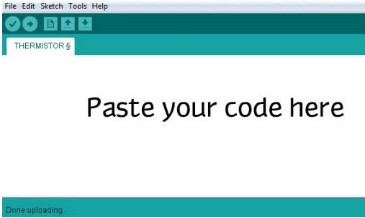
Open the IDE software on your computer to display the Compiler where you’ll paste your code as shown below.
- Paste the code into the Arduino Compiler as shown on the left
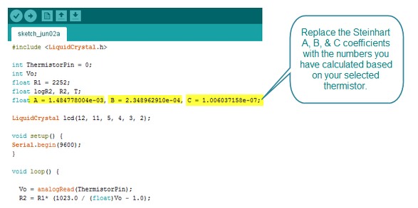
- After you’ve pasted the code, replace the existing A, B, & C coefficients with the correct ones we previously calculated based on the selected NTC thermistor as shown in the yellow highlighted area on the right
- Using the USB, connect the Arduino to your computer
- To upload the data from the IDE and send it to the Arduino board, click the (right green arrow) located top left of the screen to begin the process
- Wait approximately 10 seconds allowing all the data to transfer to the Arduino
Note: Step two is crucial to obtaining the correct A, B, & C coefficients to re-enter into the code. With that in mind, be sure to enter the correct coefficients into the code each time you use a different NTC thermistor.
Reading the Results
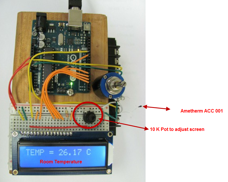
If you attached the wires correctly and entered the correct data into the IDE application, you should see your temperature reading on the LCD as shown below. Since we were looking for a room temperature between 20 ˚C & 30 ˚C, we can see that the LCD reads a temperature of 26.17 °C, which falls within our desired temperature range. Thus, we’ve accomplished our goal. You can verify the displayed temperature reading by using a standard thermometer to compare the results.
Results Not What You Expected?
Should the results fall short of your expectations, here are some tips and tricks:
- Fuzzy LCD display: To get a clear visual reading, you may have to adjust the 10k pot.
- Temperature Reading Off:
- If the displayed temperature reading is not what you expected, we recommend that you double-check your coefficient values to see that you correctly pasted them into the A, B, and C coefficient fields in the code.
- Double check your variable resistor settings and adjust if necessary. Remove the resistor from the board to re-calibrate it.
If you do find errors in your calculations, re-enter the coefficients into the Steinhart-Hart calculator then paste the correct A, B, and C coefficients into the code. You can connect the Arduino to the IDE on the computer once you have the correct code.
![]()
Well, we’ve spilled the beans about the Arduino and thermistors, and we had some fun with hardware hacking. Back to business, we understand the importance of accurate and precise temperature readings, and the critical role they play in many electrical temperature sensing applications.
Your projects are important to us, which is why we invite you to bring us your questions. We are always happy to help you find the right solution for your situation. We also invite you to test our products at no charge.
![]()
Thanks for reading! Please feel free to give us your feedback. We strive to keep you well informed.
Authored by Hiroki Hervin and Sam Kirchner

