Have you ever turned on a transformer and heard a loud humming sound? What about having a blown fuse or tripped circuit breaker? These signs can all indicate transformer inrush current.
Transformer inrush current describes a spike in current that occurs when you initially turn on your transformer. This spike can be up to 10 times higher than normal current. Why does inrush current occur? It can happen because large transformers demand a huge amount of current when energized. Until the inductive resistance and magnetic field builds, they essentially act as short circuits.This explains why you can experience distorted sounds (humming or buzzing) or blow a fuse quite easily.
Problematic Effects of Transformer Inrush Current
Inrush current in a transformer can cause several problems. Not only does it interfere with the operation of circuits, but it could result in detrimental effects to the transformer. The distortion of the volt or current waveform, known as harmonics, is another side effect of inrush current. If not properly managed, inrush current could lead to failure of circuit components, shorten the operating life of the transformer, or even cause damage.
Let’s look at the figure below. If the AC wave is going through its zero value, the current drawn will be very high and exceed the saturation current (Figure 1). In this situation, transformer inrush current protection becomes necessary to keep the transformer functioning properly.
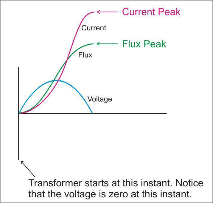
Figure 1: A transformer draws inrush current that can exceed saturation current affecting the magnetic property of the core.
Solution to Transformer Inrush Current
What is a practical solution to this problem? One convenient way to limit inrush current in a transformer is by using an NTC thermistor. The photo below shows an NTC thermistor placed in the circuit board to provide optimal inrush protection (Figure 2).
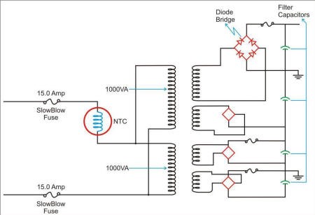
Figure 2: The NTC thermistor is placed in series with the input line to limit inrush current in a transformer.
Transformer Inrush Current Calculation
Here at Ametherm, we have a calculation that we use to help our customers select the right NTC thermistor part number. We thought we would share this with you so you can do the math for yourself, if you feel so inclined.
The 7 step process below will walk you through the calculation we performed for a 40VA transformer. You can apply these calculations to your own transformer as well. Simply enter your own application characteristics (found in step 1) and follow the equations. If you’re ready, grab a pen and paper and let’s get started!
Step 1: Define the Characteristics of Your Transformer
The 40VA transformer has the following given values. If you are doing these calculations for your own application, these values will vary.
Given Values:
- KVA or VA of transformer= 40VA
- Input voltage= 110VAC
Step 2: Write Inrush Current Assumptions
We will use the following assumptions throughout our calculations. Depending on the shape of your transformer, you will use either 10 or 30 in the first assumption (see note).
Assumptions:
- Inrush Current = 30 x Steady State Current (SSI)
- Maximum Tolerable Inrush Current = 1/5 of Inrush Current
- Frequency= 50Hz
Note:
- Use 10 x SSI if the geometry of the core is rectangular
- Use 30 x SSI if the geometry is toroidal (i.e. donut shape)
- These are typical values that we have seen based on scope traces
- The max tolerable inrush current reduces inrush current by 80
Step 3: Calculate Steady State Current of Transformer
Now that we have the given values and assumptions for our application, we are ready to start the calculations. First, we will calculate the steady state current of the transformer during normal operation by using the given values found in Step 1.
Step 4: Calculate Inrush Current
Second, we are going to calculate the inrush current caused when the transformer is powered on. You can find an explanation of this calculation in Step 2.
Step 5: Calculate Inductive Impedance
Third, we are going to calculate the inductive impedance. This is the amount of resistance the coil and core present to the electrical current.
Step 6: Calculate the Energy
Next, we will calculate the amount of energy the thermistor needs to prevent it from self-destructing.
Step 7: Calculate Minimum Cold Resistance of Thermistor
Finally, we are going to calculate the minimum cold resistance of the thermistor.
Select the Correct NTC Thermistor
Now that steps 1 through 7 are completed, you can use the voltage, SSI, and energy parameters to look up your datasheet on the chart below. The datasheet will direct you toward the correct part number for your thermistor.
For this example, we recommend using the SL03 12101 thermistor because it meets all the necessary requirements for this application.