By Balaji Santhanam, Hubble Power Systems
Mehdi Samii, Ametherm Inc.
Originally Published in Power System Design Magazine
As electronic systems continue to become more compact, temperature plays an increasingly important role in system reliability and power efficiency. Many engineers are already familiar with how temperature can affect reliability; if a system becomes too hot, device operation can become unpredictable. Using a simple temperature sensor like a thermistor, the host processor can monitor temperature and take action, such as turning on a fan when the ambient temperature is too high.
Thermistors, however, are versatile sensors that can be used for much more than just simple monitoring. This same thermistor can be used directly in-circuit with components like copper solenoids and LCDs where internal resistance varies with temperature. Other common uses of thermistors include power factor correction (PFC) and inrush surge current suppression.
![]()
Consider LCD operation. When an LCD is cold, it has a low resistance. This results in a low current through the LCD. The result is a display that is difficult to read (characters are too light) and takes a long time to warm up. Similarly, when the LCD is hot, it has a high resistance, leading to a higher current. The result is a display that is not only difficult to read (characters and background are too dark) but draws more power than it needs.
For a solenoid, less current is required to hold the solenoid open at higher temperatures. In addition, running more current than necessary through a solenoid increases the temperature of the solenoid. By reducing overall current draw, solenoid heating can be minimized, leading to a need for less frequent cooling and potentially a less expensive cooling subsystem. Running fans less frequently also reduces wear on mechanical parts, increases system reliability, and improves the user experience by running more quietly.

This article will explore how a thermistor can be used to keep current draw stable as temperature changes. Specifically, it will outline how to find the correct temperature compensation circuit for a copper coil solenoid. This cost-effective approach achieves better power efficiency for applications typically running at high temperatures, such as industrial, appliance, automotive, and other systems using temperature-sensitive components. It also improves the user experience by operating temperature-sensitive components at their ideal current (i.e. users can see the LCD clearly regardless of temperature). The approach is simple to implement and does not involve the host CPU, further improving reliability and power efficiency.
Thermistor-based Temperature Compensation
Simplicity and low cost are the key advantages of thermistors. A Negative Temperature Coefficient (NTC) thermistor, for example, provides variable resistance based on ambient temperature. This resistance follows a relatively linear response within the desired temperature range of -40 to +80° C [~120 for industrial].
In a traditional monitoring system, this allows a CPU to perform a simple table lookup to determine the temperature and compare it to a threshold to see if cooling is required. The CPU could also adjust the current to a solenoid or LCD, but this requires CPU cycles as well as additional circuitry to extend this capability to the CPU.
A simpler approach is to integrate the thermistor into an independent temperature compensation circuit. The thermistor is placed in-series with a fixed resistor. In this way, the varying resistance of the thermistor can automatically adjust how much current flows through the solenoid, LCD, or other temperature-sensitive component with no CPU involvement.
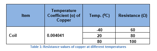
The copper coils of a solenoid exhibit a positive temperature coefficient with rising temperature. Since the NTC thermistor typically has a temperature coefficient range of -3.3% per ° C to -4.9%° per ° C, a fixed parallel resistor with temperature coefficient of 440 ppm is used to bring the temperature coefficient down to a usable limit. For example, copper has a temperature coefficient of 0.4% per °C over a temperature range of –40°C to +80°C. The coil resistance varies as 80 ± 20 ohm (see Table 1) and has the following characteristic. In addition, the coil is carrying the current of 0.85 Amp, which would also go through the thermistor causing self-heating:
![]()
![]() eqn (1)
eqn (1)
Where:
- R is the conductor resistance at temperature T
- Rref is the conductor resistance at reference temperature Tref (assumed as 20°C)
- α is the temperature coefficient of resistance for the conductor material
- T is the operating temperature of the conductor material in degrees Celsius
- Tref is the reference temperature that α is specified at for the conductor material and also signifies the midpoint temperature
- Substituting in eqn (1) yields to temperature coefficient α for copper solenoid to be .4167% per °C
Using the values from Table 1, the reference values considered are:
Tref = 20°C and Rref = 80 Ω
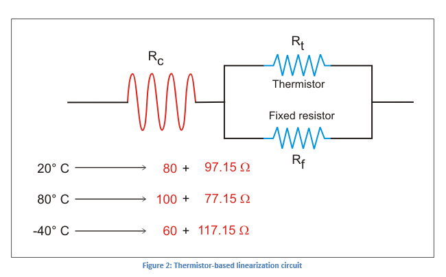
The system in consideration has a resistance in series with this pair of coils. The value of this series resistance is supposed to be 97.15 Ω based on the design in order for the system to work as expected (see Figure 1 below). Note that the total resistance is 177.15 Ω.
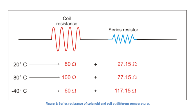
The objective is to find a temperature compensation circuit that negates the positive temperature effect of the solenoid and the series resistance. To reduce resistance fluctuation, the ideal range will be to flatten the curve at its center.
Because the responsiveness of solenoids and LCDs is sufficiently linear at the desired temperature range, a standard linearization equation can be used. This equation is basically the ratio of a fixed resistor to the resistance of the thermistor at a particular temperature (i.e. typically at the midpoint of the lowest and highest required operating temperature). In addition, accuracy is not critical for this circuit. It just needs to be able to add approximately the ideal amount of current when the solenoid is cold and reduce the current appropriately when it is hot.
Consider a linearization circuit (Figure 2) consisting of a thermistor where:
- Rc is the coil resistance that includes series resistance
- Rt is the thermistor resistance
- Rf is the fixed resistor
The total resistance of the above circuit is 177.15 + K, where
 eqn (2)
Note that the coil (with the series) resistance is 177.15 – K.
The linearization equation for flattening the curve of the thermistor is as follows:
- Fixed resistor value Rresistor = Rf
- Thermistor resistance value Rthermistor = Rt
Thus, the linearization equation:
 eqn (3)
![]()
Where:
β = material constant = in our example = 3500°K (considering Curve M, see Figure 3)
Tref, the midpoint temperature is calculated as:

The value of αtherm is calculated using the equation given below:
![]() eqn (4)
eqn (4)
Note:

Because the thermistor and fixed resistor are in parallel circuit.
Substituting for αcopper = .4167% per °C and αfixR= 440 ppm yields αtherm = -3.9% per °C

Substituting for αtherm yields β of 3412 °K
This is very close to M material in Ametherm directory of resistance temperature curves.
So, the value of fixed resistor is calculated as:
Substituting eqn (3)

Assuming the maximum deviation desired is 1.0 Ω, K = 1.0 Ω. Substituting in eqn (2) we have:

The following values are calculated:
![]()
![]()
To determine the value of the fixed resistor at 25°C, use the normalized table for material “M” to determine the normal room temperature resistance of thermistor using
 (from Table 2)
Hence:

K for the two extreme temperature conditions can be calculated as:

where 21.39 is from the normalized table multiplier to room temperature resistance of the thermistor at -40°C

where 0.1645 is from the normalized table multiplier to room temperature resistance of the thermistor at 80°C
So, the coil (with the series) resistance at:
![]()
![]()
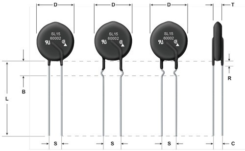
This shows that the subsystem resistance is effectively constant (i.e., stable) at ~178.1 Ω ± 0.7 Ω across the desired temperature range. The SL15 60002 thermistor from Ametherm is the chosen thermistor for this application. Table 3, Table 4, and Figure 4 provide the technical and physical details of this thermistor.

One other consideration is the physical size of the thermistor. For a larger component like a solenoid, the thermistor might introduce negligible heat compared to the solenoid. For a smaller temperature-sensitive component driving a high current, self-heating of the thermistor could introduce error by materially changing the ambient temperature. To mitigate this, a larger thermistor can be used. The larger the mass of the thermistor, the less impact self-heating has. For the example application, the solenoid was small, so the thermistor had more impact on the ambient temperature. Selecting a 15mm over a 5mm thermistor improved the performance of the compensation circuit sufficiently.
For applications already using thermistors to monitor temperature, it might be possible to implement a temperature compensation circuit with a low incremental cost. In any case, thermistors are a low-cost component. For example, an NTC thermistor costs less than 40 cents in 1K volumes and on the order of 10 cents in high volumes. Given the gains in reliability and power efficiency, this is a reasonable trade-off for many applications operating at high temperatures.
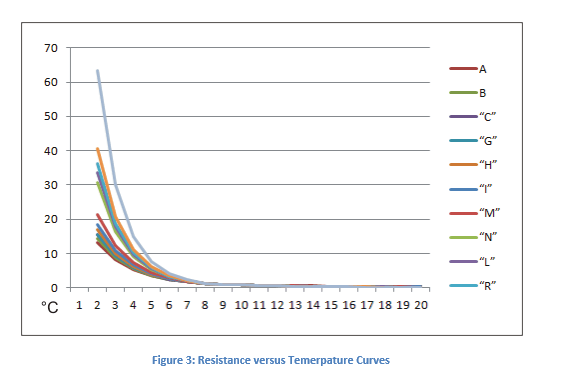
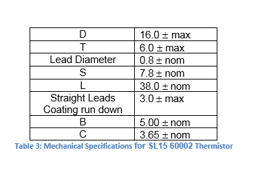
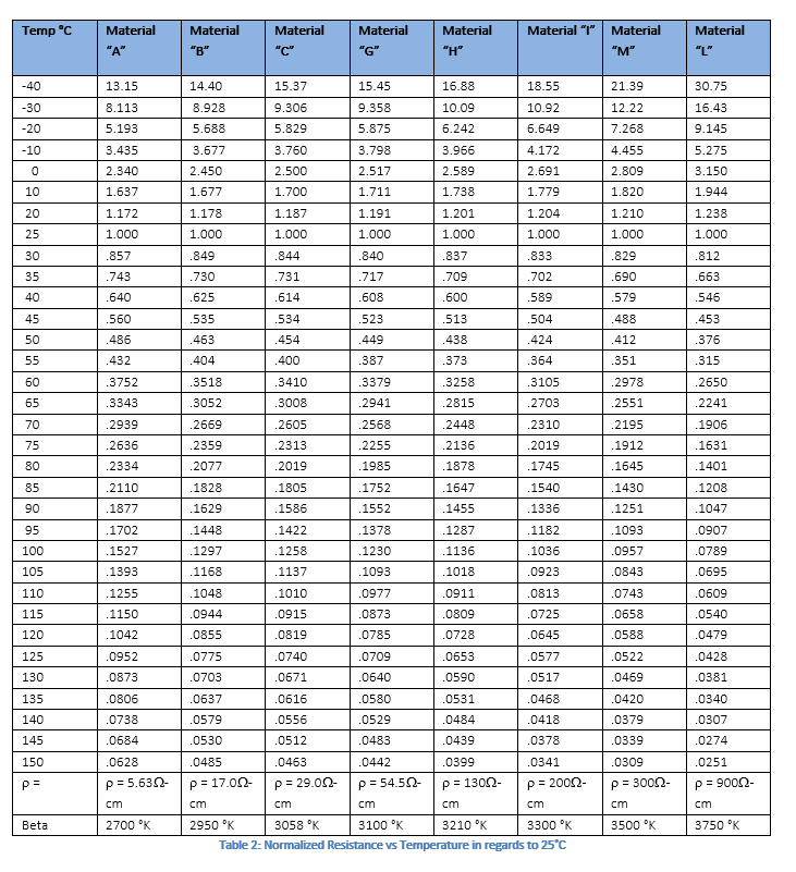
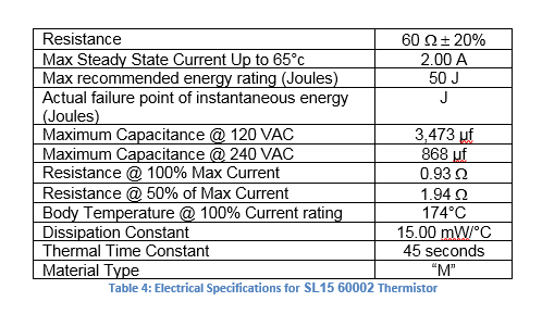
 Figure 2. Dimensions for SL15 60002 Thermistor