
Inrush current protection for LED lighting retrofits can be key to a successful lighting upgrade. Retrofit of LED lighting into an existing electrical system relies on the equipment already in place. This can be problematical due to the high inrush current created by the LED drivers.
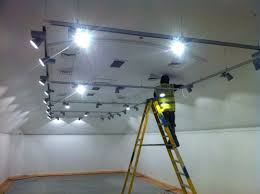
Falling LED prices and immediate energy savings are propelling the upgrade of older lighting modalities to new LED lighting for commercial and institutional users. For facilities management, benefits of a building-wide LED retrofit include energy efficiency, lower maintenance costs, reduced heat loads on HVAC systems and more lighting controllability. It would seem there is no downside to this trend, however, this lighting retrofit can have unanticipated challenges.
LED Advantage
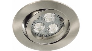
LED Luminaire Replacement for 78 Series Recessed Incandescent Light Fixture
The Light Emitting Diode (LED) is a small solid state device which converts electrical power into usable light. An LED Lamp typically utilizes multiple LEDs, mounted together in a matrix. The LED Lamp requires a special power supply, called an LED Driver, which converts AC line power into the regulated DC power required by the LEDs. When combined into a single unit, the LED Lamp and LED Driver are called a Luminaire.
The LED Luminaire can produce 138 lumens per watt. That is more than twice the 60 lumens per watt of a comparable fluorescent light fixture with magnetic ballast. The LED Luminaire has an amazing 10 times the light output per watt of an incandescent lamp.
LED lighting has several other advantages over fluorescent lighting, including no 60Hz flickering, lower heat output, ability to control light color and brightness, and extremely long service life. An LED Lamp has up to 200,000 hours of life expectancy, which is 10 times that of a fluorescent tube.
Challenge of High Inrush Current
As with any power supply, the LED Driver contains internal capacitors. For the typical LED Driver, the capacitors charge in less than one millisecond after power is turned on. This rapid charging creates inrush current which can be 100 times the LED driver’s continuous current rating. Compared to older lighting modalities, this is 6 times the inrush current of an incandescent lamp and 4 times the inrush current of the magnetic ballast used in fluorescent lighting.
Legacy electrical services were designed for older lighting modalities which had much lower inrush current. An upgrade to LED lighting can create problems for existing electrical equipment due to the LED driver’s inherent high inrush current. This can result in nuisance faulting of circuit breakers, welding of relay contacts and failure of light dimmers. The installer can be faced with derating the load previously handled by the electrical branch circuit, upgrading existing electrical equipment, or both.
Branch Circuit and LED Load
LED Lighting Retrofit Requires Planning – and Calculations to Match Load with Circuit Capacity
Lighting retrofits must observe the maximum allowable current on the building’s branch circuits. For small to medium commercial installations, this current limit is typically 20 amps for the 240VAC single-phase branch.
The total steady state current for multiple LED Drivers on a branch circuit is easily calculated when planning the lighting upgrade. For practical purposes, it is the total of the rated steady state current for all LED drivers installed on the branch. The LED Driver inrush current on the branch is also additive and is the sum of all LED Driver inrush current.
Determining the precise effect of circuit impedance and cabling resistance on branch current is outside the scope of our model. It is more important to understand that when multiple LED Drivers are installed in parallel on the same branch circuit, high inrush current must be anticipated.
Due to the limitations of legacy electrical equipment, the high inrush current of the LED lighting upgrade can be problematical. It is therefore important to approach the maximum number of LED Drivers on a branch circuit, and the resulting inrush current, conservatively. The older the building, the more important this concept becomes.
Lighting Association Guidelines
Advanced Lighting Technologies, Inc. (adlt.com), a lighting market association, has published guidelines for installation of LED Lighting Products. Their technical paper, LED Driver Inrush Currents, provides valuable data for anyone planning an LED lighting retrofit.
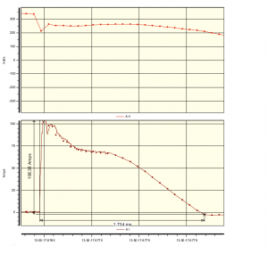
Scope traces are included and illustrate the line voltage and current of a typical LED driver at start-up. This information helps installers understand that LED lighting has power requirements different from traditional lighting modalities. An LED driver creates a high inrush current at start-up, which can be 100 times the rated continuous current. Installation of multiple LED drivers in parallel on the same branch circuit can create an inrush current sufficient to damage electrical equipment.
ALDT provides guidelines for the maximum number of LED drivers supportable on a 240V 20A commercial branch circuit: 7 to 10 drivers for typical 150W models and 6 to 8 drivers for typical 220W models. Other recommendations are given for adequately rated mains wiring and C-curve Circuit Breakers necessary to accommodate the high inrush current.
In their example, a single 220W LED driver draws 1 amp of steady state current. If the recommended maximum of 8 LED drivers is installed in parallel on the branch circuit, we would see 8 amps of steady state current. Similarly, if each LED Driver creates 100 amps of inrush current for 1 millisecond, we would see 800 amps of inrush current on the branch circuit in the first millisecond after power is turned on. Despite the short duration, this is significant inrush current and must be taken into consideration.
Single-part Solution
 Many Ametherm customers have come to us for help following their LED lighting upgrades. Installing a Thermistor Inrush Current Limiter can be an effective and economical alternative to upgrading legacy electrical equipment. Customers have been able to mitigate their LED inrush current problem with this single part solution.
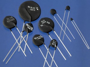
An Ametherm Thermistor Inrush Current Limiter, installed in series between the mains power and the LED Drivers, presents an additional resistance to inrush current when the circuit is energized. This additional series resistance acts to quench the inrush current. The thermistor’s resistance decreases dramatically following the inrush, allowing the steady state current to flow with very little resistance. This effect provides inrush current protection, yet allows efficiency during normal operation.
The Thermistor Inrush Current Limiter provides an ideal solution for LED lighting which is turned on once per day, as is typical in most commercial and institutional lighting applications.
Calculation Explanation
 It will be necessary to determine Three Essential Characteristics for selection of the appropriate Ametherm Thermistor Inrush Current Limiter:
- Maximum Steady State Current
- Resistance of the Thermistor
- Energy Rating of the Thermistor
Once calculated, these characteristics will be used to select the Inrush Current Limiter from the Ametherm Full Line of Inrush Current Limiters.
Calculate Maximum Steady State Current
Of the Three Essential Characteristics, Maximum Steady State Current is easiest to determine. Multiply the Steady State Current rating (sometimes called continuous current rating) of a single LED Driver, as noted in the manufacturer’s data sheet, by the total number of Drivers which will be installed on the branch circuit. In the ADLT example, the manufacturer indicates 1.05A for each 220W LED driver. With 8 Drivers planned for installation on the branch circuit, the Maximum Steady State Current is 8.4A.
Maximum Steady State Current of the LEDs on the branch circuit = (number of LED drivers on branch circuit)(steady state current rating for single LED driver) = (8 )(1.05A) = 8.4A
.
Calculate Total Inrush Current
Inrush Current and Duration of Inrush Current for LED Drivers can be different depending on manufacturer and model. For our calculation, Inrush Current for an LED Driver is 100 times the Steady State Current rating of the single LED Driver.
Inrush Current for single LED Driver = (100)(steady state current rating of single driver) = (100)(1.05A) = 105.0A
Now we need to calculate the Total Inrush Current for the 8 LED Drivers on the branch circuit. Multiply the Inrush Current of a single LED Driver, as calculated above, times the number of Drivers on the branch.
Total Inrush Current for 8 LED Drivers = (number of LED Drivers on branch circuit)(inrush current for single LED Driver) = (8)(105.0A) = 840.0A
.
Determine Maximum Allowable Inrush Current
Next, we want to establish the Maximum Allowable Inrush Current in the branch circuit. In order to prevent damage to electrical equipment, the Maximum Allowable Inrush Current must be less than the maximum current rating of the lowest rated control device the circuit. The lowest rated device will probably be a control relay or light dimmer.
For example, a light dimmer with 17.0A maximum current rating will determine the Maximum Allowable Inrush Current, even though the branch circuit may have a 20A rated circuit breaker.
Maximum Allowable Inrush Current = 17.0A
.
Calculate Minimum Resistance Required for Inrush Current Limiter
To calculate the Minimum Resistance required of the Thermistor Inrush Current Limiter, divide the Peak Voltage of the circuit by the Maximum Allowable Inrush Current. In our example, Peak Voltage is 339.3V and the Maximum Allowable Inrush Current is 17.0A.
Peak Voltage = (RMS voltage)(1.414) = (240VAC RMS)(1.414) = 339.3V
Minimum Resistance of the Thermistor Inrush Current Limiter = 339.3V / 17.0A = 19.9Ω
.
Calculate Energy in Joules for Inrush Current Limiter
The Energy Rating in Joules of the Thermistor Inrush Current Limiter must be equal to, or greater than, the total Energy of all LED Inrush Current on the branch. We will use values already calculated above for this equation.
Energy in Joules will be Peak Voltage times Inrush Current times Duration in Seconds of the Inrush Current. One millisecond duration is the same as 0.001 seconds.
Energy in Joules = (Peak Voltage)(Inrush Current)(Duration in Seconds) = (339.3V)(840.0A)(0.001S) = 285.0J
Select from Ametherm Full Line

We now have the Three Essential Characteristics required to select an Ametherm Thermistor Inrush Current Limiter:
- Maximum Steady State Current = 9A
- Minimum Resistance of Thermistor = 20Ω
- Energy Rating of Thermistor = 285J
Using Ametherm Full Line of Inrush Current Limiters table, we would select Ametherm Part Number MS35 20010.
| Part (pdf) | R@25°C | SSI Max | Joules Max | Diam (mm) | Thickness (mm) | DIGIKEY | MOUSER | NEWARK |
|---|---|---|---|---|---|---|---|---|
| MS35 20010 | 20.0 | 10.0 | 500 | 37.0 | 11.0 | 570-1026-ND | 955-MS35-20010 | 72J6632 |
- Starting on the left side of the table, locate the column R@25°C. Read down the column until you see the resistance value equal to or greater than your calculated Minimum Resistance of the Thermistor. In our example, we are looking for an Inrush Current limiter with at least 20.0 ohms of resistance.
- Next, locate the column SSI Max, which is the required Maximum Steady State Current for the Thermistor. Look down the column for an entry which has at least 9.0 Amps.
- Finally, look in the column Joules (Max) for an entry which is equal to or greater than the desired Energy rating of 285 Joules.
- Click on the Part Number in the column Part (pdf) of your selection to obtain the Data Sheet for the Ametherm Thermistor Inrush Current Limiter.
- The corresponding part number for our Authorized Online Distributors can be seen on the the rightmost side of the Full Line Table. Click these links for an easy online purchase of the Ametherm Inrush Current Limiter. An online purchase can be made by clicking the vendor’s part number under the column Digi-Key Electronics, Mouser Electronics or Newark Electronics.
Install in Series
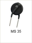 The Ametherm MS35 20010 Inrush Current Limiter must be installed in series between the mains power and the branch circuit containing the LED Drivers. The Ametherm MS35 Series Inrush Current Limiter mounts easily on DIN blocks in the power control box. DIN mounting allows the convenience of a screwdriver installation, while providing safety and protection for the Inrush Current Limiter.
.
Visit Ametherm’s Authorized Online Distributors for our other Products, Pricing and Availability.
![]()
![]()
.