Pre-Charge Circuits Prevent Damage to Inverters
Severe damage can occur to inverters when the inrush current is too great for the inverter. Pre-charge circuits protect the inverters by controlling the initial power surge. PTC thermistors can help a pre-charge circuit protect the inverter.
Inrush current occurs when the maximum instantaneous input current flows through a system when the electrical power is switched on. In power tools, such as power drives, the power supply converts the input power to the desired output power for a specific application.
Power sources receive a high voltage (VAC) signal and provide a high current output (VDC) signal. Typical input signals are 230VAC or 208VAC and output signals are10-40VDC and 30Amp to 170Amp.
Generally, a power source is designed for specific power input. The power source may not provide the same output over multiple input voltages. Components that operate at a particular input power may be damaged with the wrong input power.
To get around this issue, some manufacturers provide an automatic linkage. Such power sources test the input voltage when first connected and automatically set the proper linkage for the input source.
Inverters, batteries, and toroidal transformers need to have special control for 1-3 seconds during the initial application. This control prevents negative effects, such as circuit breaker tripping, overloading internal components, or becoming a fire hazard. The circuit that controls primary current during startup is called the pre-charge circuit.
PTC Thermistors aid in preventing severe damage to link capacitors, IGBTs, and preventing blown fuses and tripped breakers. The pre-charge PTC thermistor can stop the circuit until the correct voltage is applied and reset itself.
PTC Thermistor Protection for a Pre-Charge Circuit for Lithium-Ion Batteries
When a battery is connected to a load with capacitive input, there is an inrush current surge. The input current depends on the input capacitance: the larger the batteries and the more powerful the load, the larger the input capacitance. A large inrush current (in the pre-charge circuit, without protection) can cause the following:
- Damage to input filter capacitors
- Blow out of the main fuse
- Contact failure (and reduction in current carrying capacity) due to arcing and pitting
- Damage to the battery cell
Below is a typical pre-charge circuitry for battery operation and timing diagram, showing how the circuit operates. (Courtesy of Lithium -ION BMS)
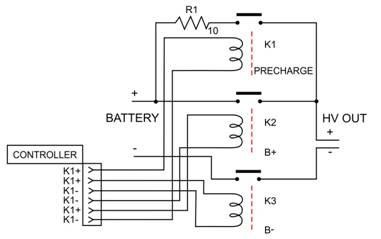
In its most basic form, the pre-charge circuit operates as follows:
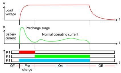
OFF: When the system is OFF all relays/contactors are off.
Precharge: When the system is first turned on, K1 and K3 are turned on to pre-charge the load until the inrush current has subsided. R1 shows the location of the thermistor in the pre-charge circuit.
ON: After pre-charge, contactor K2 is turned on (relay K1, must be off to save coil power).
Selection of the PTC Thermistor
The minimum resistance of the PTC thermistor is determined by the following:
- Ambient temperature
- Input capacitance value (of the pre-charge circuit)
- Battery voltage
The pre-charge surge current reaches 63.2% (1/ e) of its initial value after a time τ = RC.
In the selection of the PTC thermistor, we consider the time value of “five time-constant” when the capacitances are fully charged and the surge current reaches the normal operating current.
For this design, we will assume the following quantitative values:
- Precharge time: 2.50 second ± 0.50
- Ambient operating temperature: Varies between -30°C to +50°C
- Battery voltage: 100 volts
- Capacitor bank: 50,000 μF
5τ = 2.5 sec so τ = 2.5/5 = 0.50 sec
τ = RC
R = 5τ / C = 0.50 sec / 0.05F = 10.0 Ω.
Since there are various temperatures involved, it is best to utilize PTC since resistance is relatively constant between the ranges of operating temperature involved.
Therefore at -30°C the CL20 100120 will have a maximum resistance @ -30°C = 11.7 Ω, which makes the pre-charge time = 5 RC ≈ 5 (11.70(0.05F) = 2.93 sec
At 50°C, the resistance of CL20 100120 (PTC) will be ≈ 8.9 Ω, which will result in 5τ = 5(8.9Ω) (0.05F) ≈ 2.22 sec.
The max variation in time due to resistance fluctuation from -30°C to +50°C will be equal to 2.22 sec to 2.92 sec
To determine the energy the PTC thermistor needs to handle without self-destruction,
E = ½ C V2 = ½ (0.05F) (100 V)2 = 250 Joules
The steady-state current is not calculated, because in most pre-charge circuits the steady-state current goes through the contactor. The part that would meet your specification is CL20 100120.
Get CL20 100120 at Digikey.
Get CL20 100120 at Mouser.
Key benefits of Ametherm’s PTC Pre-Charge Circuit Inrush Current Limiters
- Less variation in pre-charge time due to a constant resistance within a wide temperature range.
- Faster reset time.
- Protects the circuitry from inrush currents and operator error