To use a temperature sensor in a control or compensation circuit, the detection circuit must provide an output in a usable format. For analog circuits, the output is usually a resistance. For digital control and compensation, the measurement needs to be converted to a digital format for processing by an MCU. This is commonly achieved by reading the measurement as a voltage using an analog to digital converter (ADC).
Semiconductor-based sensors typically have a digital interface, making it straightforward to communicate temperature to an MCU but not to an analog circuit. Thermocouples provide a voltage, making them readily accessible by an MCU.
Both thermistors and RTDs have the flexibility to easily provide either a resistance or voltage. This gives engineers choice in how they connect the detector to the control or compensation subsystem. As thermistors and RTDs output a variable resistance, this makes it straightforward to integrate them into an analog control or compensation circuit.
To use an NTC thermistor in a detection circuit, put a small voltage across the thermistor. The resistance of the thermistor will reflect the temperature, with its resistance dropping rapidly as temperature increases. For example, with the PANE103395 from Ametherm, the resistance of the thermistor is 10KΩ ohm at 25 °C and only 125.3 ohm at 80 °C.
If a voltage output is required, the resistance can be easily converted to a voltage using three additional resistors in a Wheatstone bridge configuration (see Figure 1).
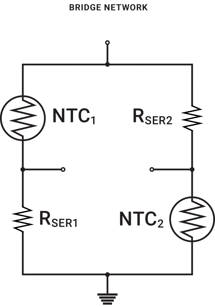
Figure 1: If a voltage output is required, the resistance from an NTC thermistor can be easily converted to a voltage using just three additional resistors in a Wheatstone bridge configuration.
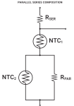
For sensors that are non-linear (e.g. thermocouples and thermistors), the output will need to go through a straightforward linearization. This can be implemented in a simple circuit for analog control and compensation (see Figure 2 and 3). For digitally based control and compensation, the measured temperature can be adjusted by the CPU using a simple table lookup that reflects the resistance/temperature chart included in the sensor’s spec sheet.

Figure 2: Sensors that are non-linear (e.g., thermocouples and thermistors) require linearization. This can be implemented for digital system using an MCU with a table lookup or for analog control and compensation circuits with a simple circuit as shown.
Engineers have many choices when designing a temperature detection circuit to prevent overheating or implement temperature control and/or compensation functionality. For extreme temperatures, thermocouples are often the best option. When the greatest accuracy is essential, platinum RTDs offer high precision. For PCB-based applications where it can be difficult to install an external sensor internally, semiconductor-based sensors make it possible to sense ambient temperature near sensitive electronics.
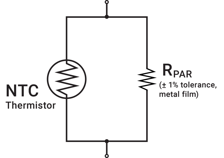
Figure 3: Thermistors and RTDs output a variable resistance, making it straightforward to integrate them into an analog control or compensation circuit. For example, a small voltage placed across the PANE103395 thermistor shown here provides a resistance that drops rapidly as the temperature
However, for applications operating in the range of -40 °C to 125 °C, NTC thermistors offer a less expensive option than platinum RTD, semiconductor-based, and even thermocouple sensors. With their fast-changing resistance based on temperature, they can provide superior accuracy, stability, power efficiency, responsiveness, and reliability. Their flexibility also makes them easy to integrate into nearly any system.